Should You Connect GND and 0VDC? Combined AC & DC Grounding
Should the DC Circuit’s Common be Connected to the Earth (Ground)?
In electrical and electronic circuit design, one of the common questions that arise is whether to connect AC Ground (GND) and 0VDC.
Meanwhile, the ground (physical earth) can be connected to 0VDC or the negative terminal of the DC system for specific reasons. However, this may introduce certain issues. Ultimately, the final decision depends on circuit requirements and applications. For example, floating AC (ungrounded AC), chassis floating, negative DC floating, or the presence (or absence) of a common ground in any part of the circuit.
Connecting the AC ground wire to the DC ground is a common practice in switched-mode power supplies (SMPS). If isolation between the DC circuit and the AC mains supply is necessary, connecting the AC ground (GND) to the 0VDC point is not recommended. Examples are, computer power supply unit (PSU), oscilloscope etc.

Grounding the negative terminal of an isolated DC system (e.g. a cellphone charger where the internal circuitry is isolated from the mains power) is generally acceptable. For example, a 2-prong plug (e.g., a mobile phone charger) used in the US typically has a floating ground, as the DC ground is not connected to the AC ground.
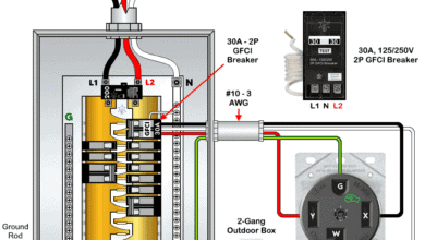
However, if the DC system is derived from the AC line through a diode rectifier and capacitor filters (e.g. voltage regulator, buck converters, inverters or a 3-prong plug (NEMA 10-30) is grounded, with the AC ground terminal connected to the DC ground) grounding the negative leg or DC common can create a ground fault. In this case, proper design of grounding and earthing is necessary according to the local area codes and manufacturer guidelines.
- Related Post: Difference Between AC Ground and DC Ground?
GND and 0VDC Grounding in NEC and IEC
According to NEC 690.41, either the negative or positive terminal of a DC system with a voltage exceeding 50V but less than 300V shall be grounded. This grounding approach is also applicable to both AC and DC grounding within photovoltaic (PV) systems in accordance with NEC 690.47(C). While the NEC suggests three methods of grounding (separate or combined), it is generally recommended to use separate grounding systems for DC systems.
This same practice aligns with international standards such as IEC 60364-7-712, BS 7671, and IEEE 80. Furthermore, lightning protection standards like IEC 62305-3 and BS 7430 recommend connecting lightning arresters to the nearest earthing rod used for the AC system.
Both the NEC and IEC emphasize the importance of separate grounding systems for both DC and AC systems to minimize the risk of ground loops, noise interference, and potential safety hazards. In short, All the electrical systems must be grounded and bonded for both AC and DC systems.
In essence, there should be only one path for fault current to return to earth. To achieve this, all equipment, devices, frames and all conductive parts within the system must be properly bonded together. A separate ground rod for this purpose is not necessary, as it can actually increase the risk of damage during lightning strikes or high-voltage transients.
For a good understanding about grounding I would suggest that you watch this video by Mike Holt. He is an absolute legend when it comes you NEC codes and electrical theory.
GND vs 0VDC
While these terms may seem interchangeable, their implications differ depending on circuit design and application.
Ground (GND)
Ground is a reference point in an electrical circuit, typically used as a common return path for electric current. It can be:
- Earth Ground: Physically connected to the earth for safety and stability.
- Chassis Ground: Connected to the metallic body of a device.
- Signal Ground: A reference voltage in electronic circuits, which may or may not be at 0V.
0VDC
In a DC system, “0VDC” refers to the zero volt direct current point. Essentially, it is the “ground” or reference point in the circuit, where the voltage is considered to be at zero potential. Alternatively, it is the common point against which all other voltages in the system are measured.
In simple words, 0VDC is the reference voltage for a DC power supply. It serves as the return path for current in a DC system and is often used as the negative terminal in a circuit. “0VDC” is often written as just “0V” or “GND” to signify the ground reference point.
Common
A common wire in DC, (also known as a neutral wire in AC), is a wire that completes an electrical circuit by returning current to the power source.
In a DC circuit, the “common” wire is typically considered the negative wire, often represented by black color coding. On the other hand, the positive wire is usually marked as red; meaning the negative wire is considered the common wire in most DC applications.
- Related Post: Difference Between GND, 0VDC, Common and Virtual Ground

Should GND and 0VDC Be Connected?
Whether to connect GND and 0VDC depends on the circuit’s application and design requirements. In most low-power electronics and DC circuits, connecting them simplifies design and enhances performance. However, in high-frequency, isolated, or AC-coupled systems, separating them may be beneficial to avoid ground loops and interference.
Usually, low-voltage DC systems do not require grounding because they pose minimal risk of electric shock or hazards. This is why it is generally safe to touch the terminals of a 12V car battery.
It is a fact that grounding AC and DC together has some advantages, but it also introduces certain challenges. However, a well-designed system can minimize these issues. Let’s see below the pro and cons of a combined AC and DC grounding.
Advantages of Connecting GND and 0VDC
Although not always a strict requirement, it’s often beneficial to understand why Distributed Control System (DCS) manufacturers recommend grounding their DC side. Connecting GND and 0VDC offers several advantages:
- Single Reference Point: Helps maintain a consistent voltage reference across the circuit, reducing floating ground issues. A common reference is required for reliable operation of the large integrate, instrumentation and control systems.
- Reduced Noise and EMI: A common ground plane reduces electromagnetic interference (EMI) and noise coupling (using “ground lift” to isolate the system GND from the earthed chassis), which is critical in sensitive electronic systems.
- Improved Signal Integrity: Ensures stable operation in mixed-signal circuits (analog and digital).
- Safety: In systems where 0VDC is connected to chassis or earth ground, it can help prevent electrical shocks by directing fault currents safely to ground. In absence of grounding, it poses a significant hazard for technicians and electricians working on the circuit, particularly when a high-voltage fault occurs and contacts the ungrounded DC circuit. Therefore, if you utilize intrinsic safety principles and employ passive barriers, grounding is must required.
- Easier Debugging: A single ground reference simplifies circuit troubleshooting and analysis.
- True Floating Ground: can be more easily maintained in systems other than DC-DC converters or battery-operated systems.
- Related Post: Difference Between Grounding, Earthing and Bonding
Drawbacks of Connecting GND and 0VDC
Despite its advantages, connecting GND and 0VDC can also present some challenges:
- Ground Loops: If multiple ground connections exist at different points, unwanted current flow (ground loops) can cause noise in the audio and voltage fluctuations.
- Fault Detection: In the absence of DC grounding, fault detection becomes almost impossible. If the positive or negative terminal of the DC system comes into contact with the ground, the fuse or breaker will not trip. Similarly, downtime will be longer in the event of a line break. This is because identifying the break becomes more challenging without a dedicated ground line.
- Increased Noise in High-Frequency Circuits: In RF and high-speed digital circuits, combined AC and DC grounding can introduce unwanted interference and performance issues. This occurs because the AC neutral is typically bonded to the earth ground. Hence, a small AC voltage (less than 1V) present on the ground conductor. When the AC and DC ground paths are interconnected, this AC voltage couples into the DC ground, creating unwanted noise within the circuit. While this noise may be negligible in low-voltage DC circuits (below 5VDC), it can significantly impact the performance of high-voltage DC systems.
- Communications Issues by Ground Loops: Ground loops can cause communication problems between a desktop and a programmable device. For example, a battery-powered laptop might function correctly, while a laptop plugged into the wall outlet may experience issues. This can occur due to a potential difference introduced into the DC ground path by the AC power connection.
- Safety Risks: If a fault occurs in AC-powered systems, connecting 0VDC to earth ground might introduce shock hazards under certain conditions. The risk of damage and safety hazards increases significantly in the event of high-voltage AC faults or lightning strikes, especially when the DC ground leg is directly connected to the AC ground.
- Interference in Isolated Circuits: In some systems, especially those with isolated power supplies, connecting GND and 0VDC can break isolation and compromise functionality.
When to Connect AC Ground to DC Ground
The decision to connect or isolate the AC ground from the DC ground depends on various factors, including safety, electromagnetic compatibility (EMC), and system performance.
Safety Compliance (Earthing for Protection)
If the DC system is housed in a metal enclosure and operates at hazardous voltages, connecting DC ground to AC ground ensures proper earthing, reducing shock hazards. NEC and IEC regulations require that all metallic and exposed conductive parts be grounded.
Electromagnetic Interference (EMI) Reduction
In some cases, a single-point connection between AC ground and DC ground can help reduce EMI by providing a common reference point and minimizing voltage differences.
Surge and Lightning Protection
If surge protectors or transient voltage suppression (TVS) devices are used, grounding the DC side to AC ground can provide a controlled path for transient currents.
Industrial Control and Power Systems
Many industrial systems (e.g., PLCs, motor drives) require a bonded AC and DC ground to maintain a stable reference potential and avoid ground loops.
Floating DC System with Proper Grounding
Some floating DC power supplies (such as battery banks) require grounding at a single point for safety and noise reduction.
Related Post: How Does the Grounding System Work in Aircraft & Submarines?
When NOT to Connect AC Ground to DC Ground
Preventing Ground Loops
Multiple ground paths may exist between AC and DC interconnected grounding circuits. The circulating currents (ground loops) can induce unwanted noise and interference, affecting sensitive electronics.
Isolated Power Supplies
If the DC system is isolated (such as an isolated DC-DC converter or transformer-based supply), connecting AC and DC ground may defeat the isolation, leading to leakage currents and safety risks.
Sensitive Measurement and Communication Circuits
In precision measurement and low-noise analog circuits (e.g., instrumentation amplifiers, sensors, audio systems), connecting AC and DC ground can introduce noise, degrading signal integrity.
Battery-Powered and Floating DC Systems
Some DC systems (e.g., battery-powered devices, solar inverters) are intentionally floating to prevent leakage currents or interference from AC mains. Grounding them improperly may cause unintended current paths.
High-Frequency and RF Systems
In RF applications, improper grounding can create unwanted resonances, signal reflection, or impedance mismatches, affecting performance.
- Related Post: Will I Get an Electric Shock If I Touch the Ground Wire?
Best Practices for Connecting GND and 0VDC
To determine the best approach, consider these best practices:
- Use a Single Point Grounding (SPG) Scheme: Minimize ground loops by ensuring all ground connections converge at a single point. Use grounding resistors or isolation transformers if direct connection is not ideal
- Implement Star Grounding in Mixed-Signal Circuits: Keep analog and digital ground planes separate, connecting them at a single point. For mixed AC/DC environments, consider capacitive or high-resistance coupling to control noise without direct grounding.
- Use Ground Planes in PCBs: A solid ground plane reduces impedance and noise issues.
- Consider Safety Standards: Follow regulatory standards (e.g., NEC, IEC) when deciding ground connections in electrical systems.
Resources:
- Why is the Grounding Wire Bare and Not Insulated?
- Why is the Ground Wire Size Smaller than the Hot Wire?
- Why is the Ground Wire Always Positioned Above the Overhead Power Lines?
- Why Must Neutral and Ground Wires Be Bonded in the Main Panel?
- Why are Neutral and Ground Wires Separated in a Subpanel?
- What Happens if a Power Line Falls into the Ocean Water?
- If Lightning Strikes the Sea, How Far Away is it Dangerous?
- What Happens to the Battery with Reverse Polarity Wiring Connection
- Will a Man Get an Electric Shock If He Hangs on a Live Wire?
- What Happens When an AC Line Touches a DC Line?
- Why are Salt and Charcoal Added in Earthing Pit for Grounding?
- Can the Neutral Wire Cause Electric Shock?
- Which One Kills – Current or Voltage and Why? Amps vs Volts
- AC or DC – Which One is More Dangerous And Why ?
- What Happens When You Touch an Electrical Busbar?
- Why Can’t We Store AC in Batteries instead of DC?
- Which One is More Dangerous? 50Hz or 60Hz in 120V/230V & Why?
- Why Do The Positive And Negative Wires Spark When Touched?
- What Happens if We Connect a Polar Capacitor the Wrong Way?
- Is Lightning AC or DC ?
- What Happens if a Battery is Connected to the AC Supply?