Sequential Motor Control Circuit Using ZEN Programable Relay
How to Run 3-Phase Motors in Sequence Using OMRON PLC – ZEN-10C1AR-A-V2 Programable Relay?
ZEN Programmable Relays are versatile and user-friendly devices used for automation and control applications. One common application is controlling the sequential operation of 3-phase motors . In this article, we will discuss the step-by-step process of running 3-phase motors in sequence using a ZEN Programmable Relay.
Hardware & Components Required
To implement the sequential motor control circuit using ZEN programable relay, the following hardware components are required:
- A ZEN Programmable Relay unit (e.g. ZEN-10C1AR-A-V2) with the necessary power supply.
- Three phase motors
- Contactors
- MCBs and MCCBs
- Auxiliary relays (if needed)
- 415V, 3-Phase & 230V 1-Phase AC Supply
- Start and Stop pushbuttons
Related Posts:
- Automatic Sequential Operations of Motors – Power, Control, PLC & Wiring Circuits
- Sequential Motor Control Circuit Using PLC S7-1200
Circuit Diagrams
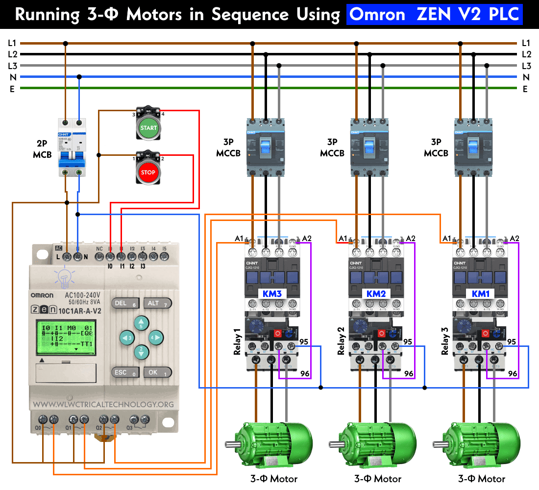
Wiring & Power Diagram
Click image to enlarge
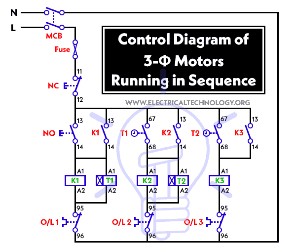
Control Diagram
Ladder Logic Diagram
Related Posts:
- Sequential Motor Control Circuit Using LOGO! V8 PLC
- Sequential Motor Control Circuit Using Delta – DVP-14SS PLC
Programming the ZEN-V2 Relay for Sequential Operation
Before proceeding with the programming steps, ensure that you have the basic understanding of relay programming concepts and the ZEN programming software.
Step 1: Hardware Setup:
- Connect the ZEN Programmable Relay to the power supply and ensure that it is properly grounded.
- Connect the necessary input and output terminals of the relay to the respective control components and 3-phase motors and contactors as shown in the power diagram.
Step 2: ZEN Programming Software:
- Install the ZEN programming software (Omron’s CX-Programmer software or ZEN-SOFT01-V4) on your computer if you haven’t already. This software is used for programming the ZEN Programmable Relay.
- Launch the software and create a new project by selecting “New” from the “File” menu.
- Configure the relay settings, such as the communication interface and address, by selecting the appropriate options.
- Define the inputs and outputs based on your hardware connections as shown on the power and ladder diagrams. For example, if you have push buttons as inputs (I0, I1, I2, I3 etc.) and contactors (KM1, KM2, KM3) as outputs (Q0, Q1, Q2, Q3, Q4 etc.), assign the appropriate addresses to them.
Step 3: Programming the Sequence:
- In the ZEN programming software, create a new ladder program by selecting the ladder editor.
- Add ladder elements such as contacts, coils, timers, and branches to the ladder program.
- Use input contacts to represent the push buttons used to start the motors.
- Use coils to represent the control signals for the contactors that activate the motors.
- Use timers to introduce the desired delay between the activation of each motor.
- Connect the ladder elements in a sequence to ensure the motors start in the desired order.
- Use branches to create conditional statements. For example, if a stop button is pressed, the sequence should stop, and all motor coils should be de-energized.
An example program based on the given operation is shown in the ladder diagram above.
Step 4: Download and Test the Program:
- Connect the ZEN Programmable Relay to your computer using the appropriate communication interface.
- Download the ladder program to the relay by selecting “Transfer” from the menu and then “Download.”
- Once the program is successfully downloaded, disconnect the relay from the computer.
- Test the sequence by pressing the start buttons and observe the activation of the contactors in the desired order. Verify that the motors start one after another with the specified time delay.
- Test the stop functionality by pressing the stop button and ensuring that all motors stop running.
Related Motor Control & Power Diagrams:
- Star – Delta Motor Control Circuit Using Omron PLC ZEN Programming Relay
- Star – Delta Starter Using Different PLCs – Wiring and Ladder Diagram
- Automatic Reverse Forward Motor Control Circuit Using Delta – DVP-14SS PLC
- Automatic Reverse – Forward Motor Control Circuit Using Omron CP2E PLC
- Star – Delta Motor Control Circuit Using Delta – DVP 14SS2 Series PLC
- Star – Delta Motor Control Using Schneider Zelio Logic PLC Smart Relay
- Reverse Forward Motor Control Circuit Using PLC – ZEN Programming Relay
- Reverse Forward Motor Control Circuit Using Mitsubishi FX Series PLC
- Automatic Reverse Forward Motor Control Using S7-1200 PLC
- Automatic Star – Delta Starter Motor Control Circuit Using LOGO! V8 PLC
- Star – Delta Starter Motor Control Circuit Using S7-1200 PLC
- STAR/DELTA Starter Without Timer – Power, Control & Wiring Diagrams
- Reverse/Forward Circuit for Motors using Start Delta & Timer – Power & Control Diagrams
- Even More Motor Control Circuits and Diagrams


