How to Size a Load Center, Panelboards and Distribution Board?
Sizing Main Panel, Load Center, Panelboards, Distribution Board & Consumer Unit According to NEC and IEC?
Planning is the first and most critical priority for all electrical wiring projects. Proper estimation and analysis, based on accurate calculations, are essential when designing and installing a power distribution system in both residential and commercial applications. This is because accurately determining the size of main panels and load center ensures they can safely and efficiently handle the current load, as well as any potential future loads.
Load centers and distribution boards should be sized in compliance with NEC, IEC, or other relevant regional codes. This process also involves selecting appropriately sized wires and cables, choosing the correct size of MCBs (Miniature Circuit Breakers), and calculating the ratings for plugs and outlets. In today’s step-by-step guide, we will demonstrate how to select the right size panelboard (whether it’s a load center, distribution board, or circuit breaker panel) according to NEC and IEC standards, with worked examples.
- Related Post: How to Determine the Right Size Capacity of a Subpanel?
Panelboard, Load Center & Distribution Board or Consumer Unit
These terms—load center, panelboard, distribution board, or consumer unit—are often used interchangeably. In short, a panelboard or distribution board is a collection of protective devices such as circuit breakers, designed to safely control and distribute electrical power to various load points, including branch and final circuits.
- Terms used in the US: Panelboard, load center, breaker box, service panel, or main electric panel.
- Terms used in the UK & EU: Distribution board (for commercial use), consumer unit (for residential use), circuit breaker box, or main panel.
We covered these topics in detail in our previous post. Now, let’s proceed to the step-by-step tutorial. The following example can also be used to determine the capacity of the main circuit breaker, as well as calculate the overall electrical load of a home.
Related Posts:
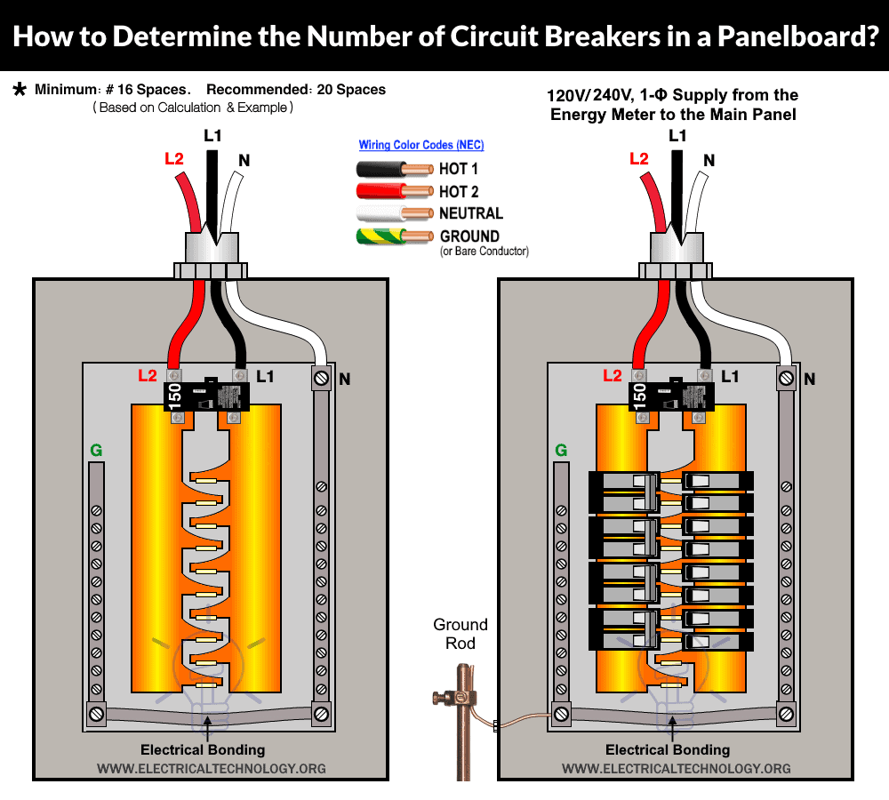
- How to Determine the Number of Circuit Breakers in a Panelboard?
- How to Find the Proper Size of Circuit Breaker? Breaker Calculator & Examples

How to Size a Main Panel & Load Center for 120/240V – NEC?
The common voltage levels for residential applications in the USA are 120V and 240V single-phase. Three wires (identified as Hot 1 with black color, Hot 2 with red color, and Neutral with white color) from the secondary side of the split-phase transformer enter the meter box and the main service panel (main switch breaker).
In this case, the available voltage in a single phase distribution system is as follow:
- Voltage between any Hot (Hot 1 or Hot 2) and Neutral = 120V
- Voltage between Hot 1 and Hot 2 = 240V
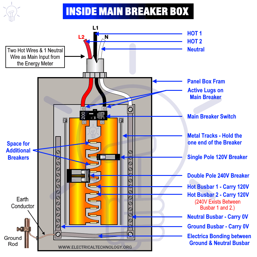
The following figure shows the overall overview of a panel box, level of voltage between different conductors and number of circuit breakers.
Click image to enlarge

Now lets see the following example to determine the suitable size of load center (or main and subpanel for electricity distribution).
Following is a general overview of a main service panel and its different parts including the space for future load points and 120V & 240V circuits.
Click image to enlarge
Example 1:
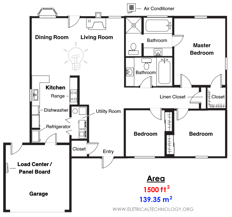
Calculate the right size of load center or main electric panel for an 1500 ft2 (square foot) or 139.35 m2 (square meters) home floor plan having the following load points:
- Air conditioner: 240V × 25A = 6000 VA = 6 kVA
- Electric range: 240V × 35A = 9600 VA = 8.4 kVA
- Electric heater: 240V × 30A = 7200 VA = 7.2 kVA
- Clothes dryer: 240V × 15A = 3600 VA = 3.6 kVA
- Dishwasher: 120V × 10A = 1200 VA = 1.2 kVA
- Garbage disposal = 120V × 8A = 960VA = 0.96 kVA
- Two Small appliances circuits in the kitchen for refrigerator, blinder, etc.
- General lighting, fans, bathroom appliances and future load etc.
Solution:
Let us find and calculate the power rating for different home appliances based on floor plan without basement and garage using NEC codes and related tables.
General Lighting Load:
The minimum general lighting load including non-appliance receptacles for home appliances e.g. TV, table light etc.) for a dwelling is 3 VA per ft2 (NEC – Article 220.41 and previous Table 220.12).
This way, the general lighting load for 1800 ft2 (given in example):
3 VA × 1500 ft2 = 4500 VA = 4.5 kVA
Small Appliances Load
There should be at least two 120V, 20A small appliance circuits i.e. in the kitchen for small appliances such as coffee maker & toasters etc. (NEC Article 210.11(C)(1). These circuits should be rated at 1.5 kVA (NEC Article 220.52(A). This way, the small appliances loads in the given example house:
2 × 1500 VA = 3000 VA = 3 kVA
Laundry Circuit
There should be at least one 120V, 20A circuit for the laundry area (NEC Article 210.11(C)(2). The minimum VA rating of the laundry circuit should be 1.5 kVA (NEC Article 220.52(B). This way, the load rating in the laundry area:
1500 VA = 1.5 kVA
This way, the total general lighting and small appliances including laundry circuit rating:
- General lighting = 4.5 kVA
- Small appliance load = 3 kVA
- Laundry circuit = 1.5 kVA
Total of general lighting and small appliances:
= 4.5 kVA + 3 kVA + 1.5 kVA = 9 kVA
Demand Factor
As we know that all electrical appliances are not operational at once i.e. (only one can be used as either electric heater or refrigerator depending on the temperature). Similarly, all equipment are not always ON continuously such as electric iron, water heater, lighting, fans etc. For this reason, the first 3 kVA (of the total load for floor area calculated according 220.5(C)) is rated at 100% while the remaining load can be rated at a demand factor of 35% (NEC Table 220.45). This way;
- The first 3 kVA at 100% = 3 kVA
- Remaining 6 kVA (9 kVA – 3 kVA) at 35% = 2.1 kVA
Net total of general lighting and small appliances;
= 3 kVA + 2.1 kVA = 5.1 kVA
Large Appliance Loads
High power rating e.g. large appliances with continuous and non-continues operation should be handled differently. We have the following high power rated appliances in the above example:
- Air conditioner: 240V × 25A = 6 kVA
- Electric range: 240V × 35A = 8.4 kVA
- Electric heater: 240V × 30A = 7.2 kVA
- Clothes dryer: 240V × 15A = 3.6 kVA
As we have already mentioned above, an air conditioner or electric heater can be used at the same time i.e. only one appliance is needed to operate based on the temperature. In this case, appliances with larger ratings should be taken into account (NEC® Article 220.82(C)). In our example, the rating of electric heater (7.2 kVA) is greater than the air-conditioner (6 kVA), so we will consider the heater then, i.e. 7.2 kVA
The rest of the appliances should be rated at 100% except electric range as it is used for a short time i.e. it is non-continuous as compared to other appliances. The allowable demand factor for 7.2 kW electric heater is 5.76 kW (NEC Table 220.55). We assumed the power factor is unity i.e. “1” where apparent power = real power e.g. kVA = kW. This way;
- Electric range: = 8.4 kVA
- Electric heater = 5.76 kVA
- Clothes dryer: = 3.6 kVA
Net total of large rated appliances:
= 8.4 kVA + 5.76 kVA + 3.6 kVA = 17.76 kVA
Miscellaneous Loads
The miscellaneous loads given in the example are:
- Dishwasher = 1.2 kVA
- Garbage disposal = 0.96 kVA
Net miscellaneous load rating:
= 1.2kVA + 0.96 kVA = 2.16 kVA
Total Load
| Load Points | kW or kVA Rating |
| General lighting, laundry & small load | 5.1 kVA |
| Net large appliance load | 17.76 kVA |
| Miscellaneous appliance load | 2.16 kVA |
| Total Load | 25.02 kVA |
Required Service
The common supply voltage levels in the US supplied to residential homes are 120V/240V. Thus, we may use the highest level of voltage to determine the required service (for amps) by using the following formula.
I = P / V
Where:
Putting the values;
I = 25.02 kVA / 240V
I = 104.25A
It means, the required service is 105A. But we have to add the future expansion and safety factor as well.
Future Load:
It is important to add a space of at least two branch circuits for the future expansion. The minimum of 2 breakers each of min 10A space should be added i.e. 2 × 10A = 20A
The total Amps = 20A + 104.25A = 124.25A
Safety Factor
It is recommended to add a safety factor of 20% to the total amperage as circuit breakers and their operations in the load center are affected by the rise in the temperature. This way, the total current in the amperes:
Net total Amps = 20% + 124.25A = 149A
The suitable size of load center or main panel = 150 Amperes
Based on the above calculations, the right size of load center or panelboard is 150A which is nearest available to the calculated value.
Click image to enlarge
For this 150A main panel, the right wire size for service is #1 AWG Copper or #2/0 AWG Aluminum based on 83% rule in NEC – Table 310.12(A). The minimum size for Ground wire is #8 AWG Copper or #6AWG Aluminum.
Related Posts:
- How to Wire 120V & 240V Main Panel? Breaker Box Installation
- How to Wire a Subpanel? Main Lug Installation for 120V/240V
- How to Wire 277V & 480V, 1-Phase & 3-Phase, Commercial Main Service Panel?
- It is always a good practice to follow the NEC guidelines for main panel, main lug or load center requirement and installation.
- The main breaker feeding the busbar can not exceed busbar rating in the main panel or load center. (NEC – 705.12(B)(2)(3).
- Sum of the ampacity of all the overcurrent protection devices i.e. breakers can not exceed the busbar ampacity rating. (NEC 705.12(B)(3)).
- The NEC allows exceeding the busbar’s rating by up to 120% except the rating of OCPD protecting the busbar and 125% of the power source output circuit amperes.
- This above calculation are based on the NEC guidelines. For more details, refer to NEC 210.21, 210.24, 220.110, 220.14, 220.42, 220.45, 220.53, 220.55, 240.4, 310.12, 310.12, 310-14 and 517.22
How to Size a Consumer Unit? Single-Phase, 230V – IEC
The following example will show you how to find the right size of single phase 230V AC consumer unit or garage unit and associated MCB/MCCB to handle the residential load.
- It is a good practice to follow the IEC and IEC guidelines and requirements for consumer unit, garage unit and distribution board installation
Example 2:
Find the proper size of a single phase consumer unit if the estimated total load in a home is 12 kVA.
Solution:
Generally, the power factor of residential homes having normal loads is considered as unity “1”. This way, the total load in kVA = kW i.e. the apparent power is equal to the real power in watts due to the absence of power factor.
Now, we will have to first calculate the load current using the general formula of current in amperes for single phase circuits.
First of all, we will find the required amperes by using the three phase current formula.
P = V × I × Cos Ф
I = P ÷ (V × Cos Ф)
Putting the values:
I = 12 kW ÷ 230V
I = 52.17A
Diversity Factor:
The general diversity factor is 80% of the connected load for residential applications. (You may select the proper % according to the load type in the IEC 60439). In this case,
80% × 52.17A = 41.74 A
Future Expansion:
The general rule of thumb for safety factor is 20%. So you may add it as well if needed.
20% × 41.74A = 50 A
Safety Factor
The minimum safe range of the safety factor is 20-25%. So we will it add it to the calculated value of load current as follows:
25% × 50 A = 62.5 A
This way, we may select the nearest standard available rating of MCCB which is 63A for the single phase 230V consumer unit. Based on the calculation, this 63A MCB or MCCB is the right size to handle a 12kW load in residential homes.
Related Posts:
- How to Wire Single-Phase, 230V Consumer Unit with RCD? IEC, UK & EU
- How to Wire a Garage Consumer Unit?
- How to Wire 1-Phase Split Load Consumer Unit? – RCD+RCBO
- How to Wire 230V Dual Split Load Consumer Unit? – RCD+MCB
How to Size a Distribution Board? 3-Phase, 400V – IEC
In the following example, we will show you how to calculate the right size of three phase 400V distribution board which is mostly applicable in countries following the IEC rules e.g. UK, EU and former British colonies.
Good to Know: It is
Example 3:
What is the right size of a three phase distribution board if the estimated total load in a home is 50 kVA. The load is a combination of single phase and three phase systems (400V & 230V AC) including air-conditioning, refrigerator, electric range, water pumps, washing machines and general lighting points etc. Consider the power factor = 0.9.
Solution:
First of all, we will find the required amperes by using the three phase current formula.
P = √3 × V × I × Cos Ф
I = P ÷ (√3 × V × Cos Ф)
Substituting the values:
I = 50kW ÷ (√3 × 400V × 0.9)
I = 80.18A
Diversity Factor:
The general diversity factor based on IEC is 80% for mixed load in residential applications. (see IEC 60439 for more details). In this case,
80% × 80.18A = 64.15 A.
Future Expansion:
The general rule of thumb for safety factor is 20%. You may add it accordingly when needed.
20% × 64.15A = 76.98 A
Safety Factor
The minimum safe range of the safety factor is 20-25%. It may also be used as future expansion if needed. Just add it to the calculated value of the load current as follows:
25% × 76.98 A = 96.22 A
Now, the nearest standard available rating of MCCB shall be 100A for the three phase 400V distribution board which is the suitable size to handle a 50 kW load.
Related Posts:
- How to Wire a Three Phase, 400V Distribution Board? IEC & UK
- How to Wire Combo of 3-Φ & 1-Φ, 400V/230V Distribution Board?
- How to Wire 3-Phase & 1-Phase Split Load Distribution Board?
Following are more related resources and step by step guide tutorials with solved examples:
- How to Find the Right Wire Size for 100A Service 120V/240V Panel?
- What is the Right Wire Size for a 4.8kW, 240V Range: #10 or #12?
- How to Find The Suitable Size of Cable & Wire ? – Solved Examples
- How to Find Voltage & Ampere Rating of Switch, Plug, Outlet & Receptacle
- How to Read MCB Nameplate Data Rating Printed on it?
- How to Wire a Single Element Water Heater and Thermostat?
- How to Find the Size of Earth Conductor, Earthing Lead & Earth Electrodes?
- Wire & Cable Size Calculator in AWG
- Electrical Wire & Cable Size Calculator (Copper & Aluminum)


