Difference Between Real Ground and Virtual Ground
What is the Difference Between Real Ground and Virtual Ground?
Real ground refers to a physical connection between the metallic body of a device to the earth or ground through ECG and GEC or Earth continuity conductor. In contrast, virtual ground is a concept used in operational amplifiers (op-amps), where a node is assumed to have the same potential as the ground terminal, even though it is not physically connected to it.
Real Ground
A real ground (also called actual ground or earth ground) is a direct physical connection to the Earth or a common reference point in an electrical system. It is typically used for safety, providing a return path for fault currents and preventing electrical shocks. In circuit schematics, it is represented by the ground symbol (⏚ or ⏋).
For example, as required by the National Electrical Code (NEC) Article 250, all metallic and exposed parts must be connected to a ground rod via an Equipment Grounding Conductor (EGC) and a Grounding Electrode Conductor (GEC). Similarly, the neutral wire in an electrical panel is often bonded to the earth ground. In electrical wiring installations, a green or bare conductor is used for grounding.
In IEC and BS 7671 standards, the concept and purpose of earthing are the same as grounding in the NEC and CEC, but different terminology is used. For instance, the metallic parts of equipment are connected to an earth plate via an Earth Continuity Conductor (ECC). A green or green-with-yellow-stripe wire is used for Protective Earth (PE).
-
Good to Know: Grounding systems are required in both AC and DC systems according to NEC Article 250, NEC 690.41, NEC 690.47, IEC 60364, BS 7430, and IEEE 80.
Virtual Ground
A virtual ground is a point in a circuit that is maintained at a fixed reference voltage (often 0V) but is not actually connected to the Earth. It is commonly used in op-amp circuits, where one input is held at a constant voltage to create a stable reference.
Unlike real ground, virtual ground does not absorb current directly but serves as a potential reference. For example, In an op-amp inverting amplifier, the non-inverting terminal is grounded, and the inverting terminal becomes a virtual ground due to negative feedback.
In negative feedback configurations, the virtual ground concept is only applicable when both terminals have the same voltage, and neither terminal acts as an actual ground.
For instance, in operational amplifiers (op-amps), the virtual ground concept applies only to negative feedback configurations. In other words, virtual ground is not applicable in positive feedback configurations, such as a Schmitt trigger. Instead, it is observed in negative feedback op-amp circuits like inverting and non-inverting amplifiers, voltage followers, etc.
As shown in the figure below of a non-inverting op-amp (with negative feedback), V1 is connected to the real ground, which has zero potential, allowing current to flow to the negative terminal of the supply source. V2 is connected to the virtual ground, which maintains zero potential. However, while current flows to other nodes, it does not pass to the negative terminal of the supply source.
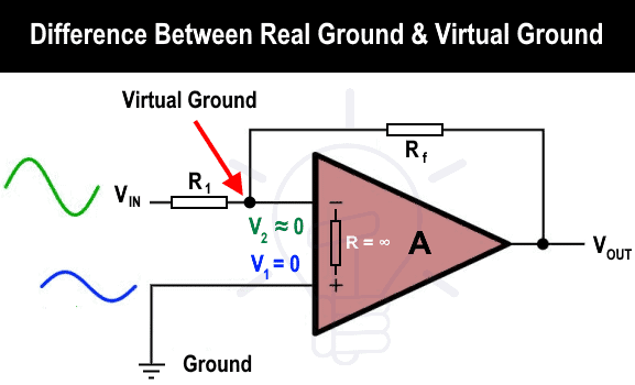
In short, V2 does not sink current because the current at node V2 flows through the feedback resistor (Rf) and VOUT due to the high resistance of “R” in the op-amp. Therefore, the V2 node acts as a virtual ground, while V1 is connected to the real ground.
Key Differences Between Real and Virtual Ground
The following comparison table shows the main differences between virtual and real ground.
| Feature | Real Ground | Virtual Ground |
| Physical Connection | Directly connected to Earth or system ground | Not physically connected to Earth |
| Current Flow | Can sink or source current | Usually does not sink/source significant current |
| Purpose | Safety, fault current path, and reference | Used for circuit operation and voltage reference |
| Example | Electrical grounding in a power system | Op-amp inverting terminal in certain configurations |
- Related Post:
Related Posts:
- Why Earth Pin is Thicker and Longer in a 3-Pin Plug?
- What is the Difference Between Neutral, Ground and Earth?
- Difference Between Grounding, Earthing and Bonding
- Difference Between AC Ground and DC Ground
- Difference Between GND, 0VDC, Common and Virtual Ground
- Can you Combine AC and DC Ground in a Solar Installation?
- Should You Connect GND and 0VDC? Combined AC & DC Grounding
- Why Doesn’t DC System Require a Grounding System Similar to AC System?
- How Does the Grounding System Work in Aircraft & Submarines?
- Will I Get an Electric Shock If I Touch the Ground Wire?
- Why is the Grounding Wire Bare and Not Insulated?
- Why is the Ground Wire Size Smaller than the Hot Wire?
- Why Must Neutral and Ground Wires Be Bonded in the Main Panel?
- Why are Neutral and Ground Wires Separated in a Subpanel?
- Why are Salt and Charcoal Added in Earthing Pit for Grounding?
- What is the Purpose of Ground Wire in Overhead Transmission Lines?
- Why is the Ground Wire Always Positioned Above the Overhead Power Lines?


Thanks.
Ok