How to Calculate the Suitable Capacitor Size in µ-Farads & kVAR for P.F Improvement
How to Find the Right Size Capacitor Bank Value in both kVAR and Microfarads for Power Factor Correction – 3 Methods
As we got lots of emails and messages from the audience to make a step by step tutorial which shows how to calculate the proper size of a capacitor bank in kVAR and micro-farads for power factor correction and improvement in both single phase and three phase circuits.
This article will show how to find the right size capacitor bank in both Microfarads and kVAR to improve the existing “i.e. lagging” P.F to the targeted “i.e. desired” as corrected power factor has multiple advantages. Below, we showed three different methods with solved examples to determine the exact value of capacitance of a capacitor for P.F correction.
Now let’s begin and consider the following examples…
How to Calculate the Capacitor Value in kVAR?
Example: 1
A 3 Phase, 5 kW Induction Motor has a P.F (Power factor) of 0.75 lagging. What size of Capacitor in kVAR is required to improve the P.F (Power Factor) to 0.90?
Solution #1 (Simple Method using the Table Multiplier)
Motor Input = 5kW
From Table, Multiplier to improve PF from 0.75 to 0.90 is 0.398
Required Capacitor kVAR to improve P.F from 0.75 to 0.90
Required Capacitor kVAR = kW x Table 1 Multiplier of 0.75 and 0.90
= 5kW x 0.398
= 1.99 kVAR
And Rating of Capacitors connected in each Phase
= 1.99kVAR / 3
= 0.663 kVAR
Solution # 2 (Classic Calculation Method)
Motor input = P = 5 kW
Original P.F = Cosθ1 = 0.75
Final P.F = Cosθ2 = 0.90
θ1 = Cos-1 = (0.75) = 41°.41; Tan θ1 = Tan (41°.41) = 0.8819
θ2 = Cos-1 = (0.90) = 25°.84; Tan θ2 = Tan (25°.50) = 0.4843
Required Capacitor kVAR to improve P.F from 0.75 to 0.90
Required Capacitor kVAR = P (Tan θ1 – Tan θ2)
= 5kW (0.8819 – 0.4843)
= 1.99 kVAR
And Rating of Capacitors connected in each Phase
1.99 kVAR / 3 = 0.663 kVAR
Note: Tables for Capacitor Sizing in kVAr and microfarads for PF Correction
The following tables (given at the end of this post) have been prepared to simplify kVAR calculation for power factor improvement. The size of capacitor in kVAR is the kW multiplied by factor in table to improve from existing power factor to proposed power factor. Check the others solved examples below.
Example 2:
An Alternator is supplying a load of 650 kW at a P.F (Power factor) of 0.65. What size of Capacitor in kVAR is required to raise the P.F (Power Factor) to unity (1)? And how many more kW can the alternator supply for the same kVA loading when P.F improved.
Solution #1 (Simple Table Method using Table Multiple)
Supplying kW = 650 kW
From Table 1, Multiplier to improve PF from 0.65 to unity (1) is 1.169
Required Capacitor kVAR to improve P.F from 0.65 to unity (1).
Required Capacitor kVAR = kW x Table 1 Multiplier of 0.65 and 1.0
= 650kW x 1.169
= 759.85 kVAR
We know that P.F = Cosθ = kW/kVA . . .or
kVA = kW / Cosθ
= 650/0.65 = 1000 kVA
When Power Factor is raised to unity (1)
No of kW = kVA x Cosθ
= 1000 x 1 = 1000kW
Hence increased Power supplied by Alternator
1000kW – 650kW = 350kW
Solution # 2 (Classic Calculation Method)
Supplying kW = 650 kW
Original P.F = Cosθ1 = 0.65
Final P.F = Cosθ2 = 1
θ1 = Cos-1 = (0.65) = 49°.45; Tan θ1 = Tan (41°.24) = 1.169
θ2 = Cos-1 = (1) = 0°; Tan θ2 = Tan (0°) = 0
Required Capacitor kVAR to improve P.F from 0.75 to 0.90
Required Capacitor kVAR = P (Tan θ1 – Tan θ2)
= 650kW (1.169– 0)
= 759.85 kVAR
How to Calculate the Capacitor Value in Microfarad & kVAR?
The following methods show that how to determine the required capacitor bank value in both kVAR and Micro-Farads. In addition, the solved examples also show that how to convert the capacity of a capacitor in microfarad to kVAR and kVAR to microfarad for P.F. This way, a right size capacitor bank can be installed in parallel to each phase load side to obtain the targeted power factor.
Example: 3
A 500 volts 60 c/s single phase motor takes a full load current of 50 amp at P.F 0.86 lagging. The motor power factor has to be improved to 0.94 by connecting capacitor bank across it. Calculate the required capacity of capacitor in both kVAR and μ-Farads?
Solution:
(1) To find the required capacity of Capacitance in kVAR to improve P.F from 0.86 to 0.94 (Two Methods)
Solution #1 (Table Method)
Motor Input = P = V x I x Cosθ
= 500V x 50A x 0.86
= 21.5kW
From Table, Multiplier to improve PF from 0.86 to 0.94 is 0.230
Required Capacitor kVAR to improve P.F from 0.86 to 0.94
Required Capacitor kVAR = kW x Table Multiplier of 0.86 and 0.94
= 21.5kW x 0.230
= 4.9 kVAR
Solution # 2 (Calculation Method)
Motor Input = P = V x I x Cosθ
= 500V x 50A x 0.86
= 21.5kW
Actual or existing P.F = Cosθ1 = 0.86
Required or target P.F = Cosθ2 = 0.94
θ1 = Cos-1 = (0.86) = 30.68°; Tan θ1 = Tan (30.68°) = 0.593
θ2 = Cos-1 = (0.95) = 19.94°; Tan θ2 = Tan (19.94°) = 0.363
Required Capacitor kVAR to improve P.F from 0.86 to 0.95
Required Capacitor kVAR = P in kW (Tan θ1 – Tan θ2)
= 21.5kW (0.593 – 0.363)
= 4.954 kVAR
(2) To find the required capacity of Capacitance in Farads to improve P.F from 0.86 to 0.97 (Two Methods)
Solution #1 (Table Method)
We have already calculated the required Capacity of Capacitor in kVAR, so we can easily convert it into Farads by using this simple formula
Required Capacity of Capacitor in Farads/Microfarads
- C = kVAR / (2π x f x V2) in Farad
- C = kVAR x 109 / (2π x f x V2) in Microfarad
Putting the Values in the above formula
= (4.954 kVAR) / (2 x π x 60Hz x 5002V)
= 52.56 μF
Solution # 2 (Calculation Method)
kVAR = 4.954 … (i)
We know that;
IC = V / XC
Whereas XC = 1 / 2π x f x C
IC = V / (1 / 2π x f x C)
IC = V x 2π x f x C
= (500V) x 2π x (60Hz) x C
IC = 188495.5 x C
And,
kVAR = (V x IC) / 1000 … [kVAR = ( V x I) / 1000 ]
= 500V x 188495.5 x C
IC = 94247750 x C … (ii)
Equating Equation (i) & (ii), we get,
94247750 x C = 4.954 kVAR x C
C = 4.954 kVAR / 94247750
C = 78.2 μF
Example 4
What value of Capacitance must be connected in parallel with a load drawing 1kW at 70% lagging power factor from a 208V, 60Hz Source in order to raise the overall power factor to 91%.
Solution:
You can use either Table method or Simple Calculation method to find the required value of Capacitance in Farads or kVAR to improve Power factor from 0.71 to 0.97. So We used the table method in this case.
P = 1000W
Actual Power factor = Cosθ1 = 0.71
Desired Power factor = Cosθ2 = 0.97
From Table, Multiplier to improve PF from 0.71 to 0.97 is 0.741
Required Capacitor kVAR to improve P.F from 0.71 to 0.97
Required Capacitor kVAR = kW x Table Multiplier of 0.71 and 0.97
= 1kW x 0.741
= 741 VAR or 0.741 kVAR (required Capacitance Value in kVAR)
Current in the Capacitor =
IC = QC / V
= 741kVAR / 208V
= 3.56A
And
XC = V / IC
= 208V / 3.76 = 58.42Ω
C = 1/ (2π x f x XC)
C = 1 (2π x 60Hz x 58.42Ω)
C = 45.4 μF (required Capacitance Value in Farads)
Capacitor kVAR to μ-Farad & μ-Farad to kVAR Conversion
The following formulas are used to calculate and convert capacitor kVAR to Farads and Vice Versa.
Required Capacitator in kVAR
Convert Capacitor Farads & Microfarads in VAR, kVAR and MVAR.
- VAR = C x 2π x f x V2x 10-6 … VAR
- VAR = C in μF x f x V2 / (159.155 x 10³) … in VAR
- kVAR = C x 2π x f x V2 x 10-9 … in kVAR
- kVAR = C in μF x f x V2 ÷ (159.155 x 10⁶) … in kVAR
- MVAR = C x 2π x f x V2 x 10-12 … in MVAR
- MVAR = C in μF x f x V2 ÷ (159.155 x 10⁹) … in MVAR
Required Capacitor in Farads/Microfarads.
Convert Capacitor kVAR in Farads & Microfarads
- C = kVAR x 103 / 2π x f x V2 … in Farad
- C = 159.155 x Q in kVAR / f x V2 … in Farad
- C = kVAR x 109 / (2π x f x V2) … in Microfarad
- C = 159.155 x 10⁶ x Q in kVAR / f x V2 … in Microfarad
Where:
- C = Capacitance in Microfarad
- Q = Reactive Power in Volt-Amp-Reactive
- f = Frequency in Hertz
- V = Voltage in Volts
Good to Know:
Following are the important electrical formulas used in Power factor improvement calculation.
Active Power (P) in Watts:
- kW = kVA x Cosθ
- kW = HP x 0.746 or (HP x 0.746) / Efficiency … (HP = Motor Horse Power)
- kW = √ ( kVA2 – kVAR2)
- kW = P = V x I Cosθ … (Single Phase)
- kW = P = √3x V x I Cosθ … (Three Phase Line to Line)
- kW = P = 3x V x I Cosθ … (Three Phase Line to Phase)
Apparent Power (S) in VA:
- kVA = √(kW2 + kVAR2)
- kVA = kW / Cosθ
Reactive Power (Q) in VA:
- kVAR = √(kVA2 – kW2)
- kVAR = C x (2π x f x V2)
Power Factor (from 0.1 to 1)
- Power Factor = Cosθ = P / V I … (Single Phase)
- Power Factor = Cosθ = P / (√3x V x I) … (Three Phase Line to Line)
- Power Factor = Cosθ = P / (3x V x I) … (Three Phase Line to Neutral)
- Power Factor = Cosθ = kW / kVA … (Both Single Phase & Three Phase)
- Power Factor = Cosθ = R/Z … (Resistance / Impedance)
And
- XC = 1 / (2π x f x C) … (XC = Capacitive reactance)
- IC = V / XC … (I = V / R)
Related Posts:
Capacitor Bank Sizing & PF Correction Calculators
If the above two methods seem a little bit tricky (which should not at least), you may then use the following online power factor kVAR and microfarads calculators made by our team for you.
- μ-Farad to kVAR Calculator
- kVAR to Farad Calculator
- Capacitor Bank in kVAR & µF Calculator
- Power Factor Correction Calculator – How to Find P.F Capacitor in µF & kVAR?
- How to Convert Capacitor μ-Farads to kVAR and Vice Versa? For P.F Correction
Capacitor Sizing Chart & Table for Power Factor Correction
The following power factor correction chart can be used to easily find the right size of capacitor bank for desired power factor improvement. For example, if you need to improve the existing power factor from 0.6 to 0.98, just look at the multiplier for both figures in the table which is 1.030. Multiply this number with the existing active power in kW. You can find the real power by multiplying the voltage to the current and the existing lagging power factor i.e. P in Watts = Voltage in volts x Current in Amps x Cosθ1. This easy way, you will find the required value of capacitance in kVAR which is needed to get the desired power factor.
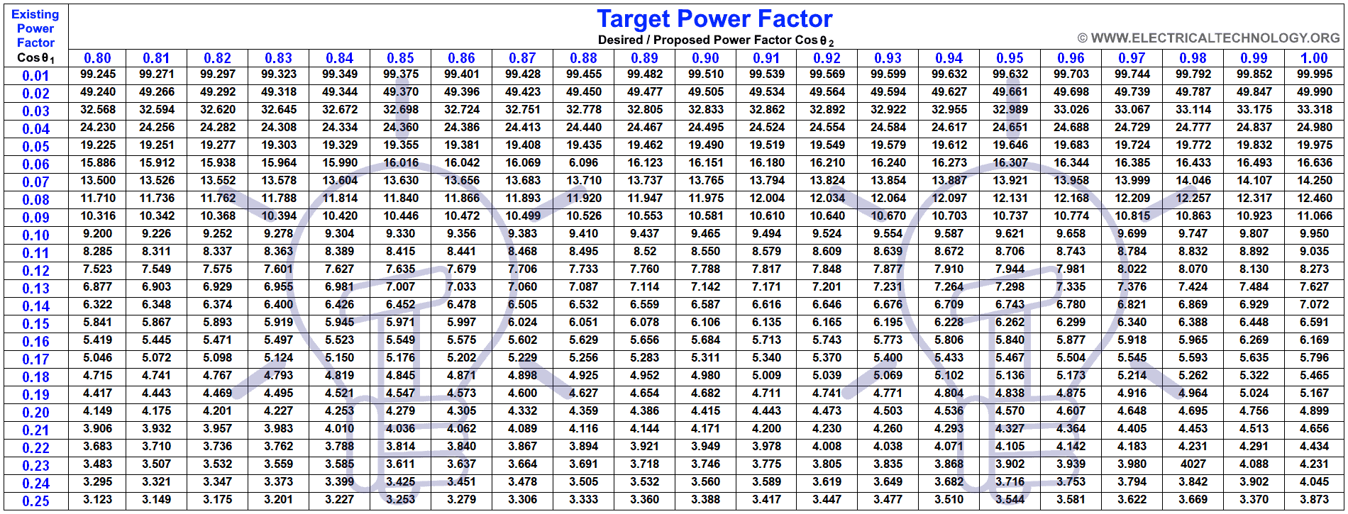
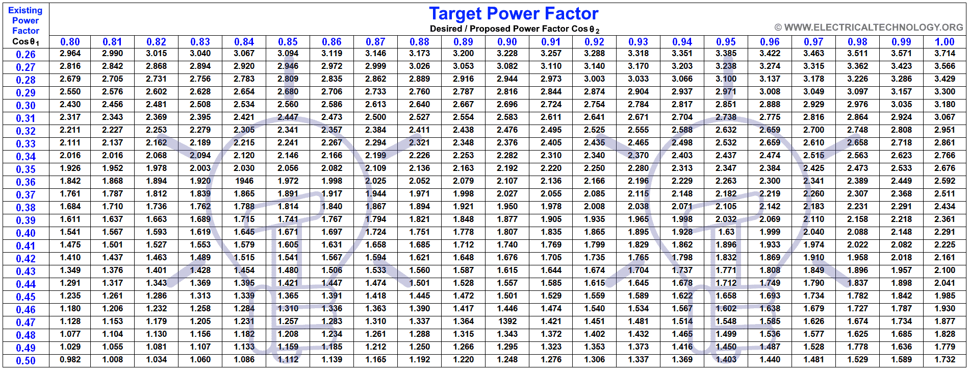
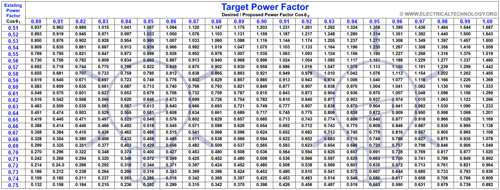
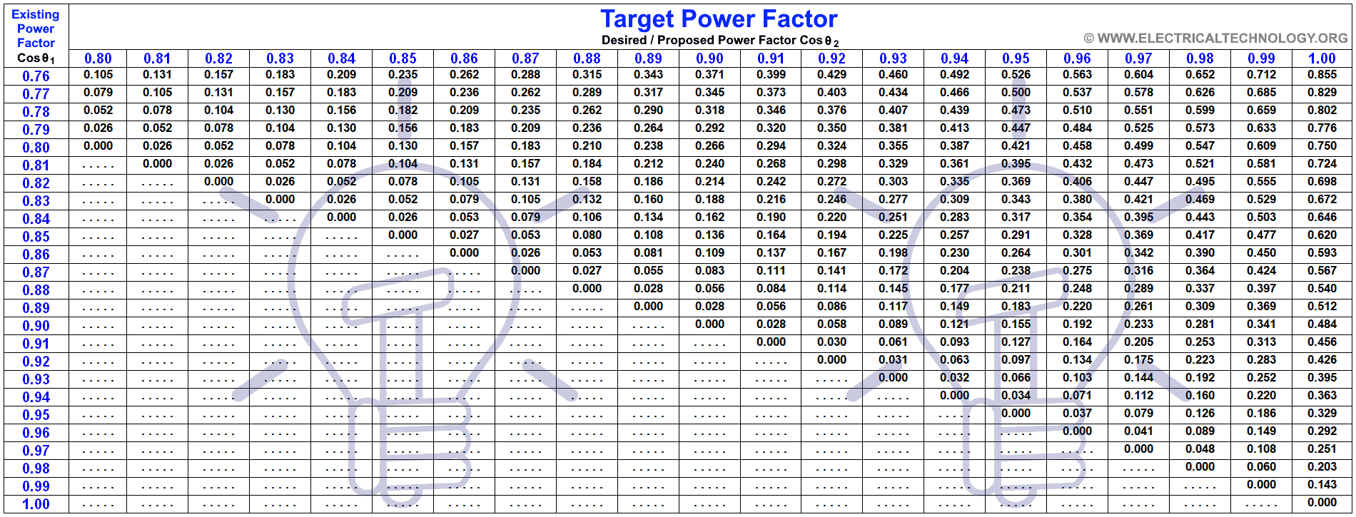
Here is the whole table if you need it to download as a reference.

Related Posts
- Power Factor improvement Methods with Their advantages & Disadvantages
- How to calculate the value of resistor for LED’s (with different types of LED’s circuits)
- How to Calculate the Rating of Transformer in kVA (1 Phase and 3 Phase)?
- How To Calculate Your Electricity Bill. Easy Explanation with Calculator
- How to Find The Suitable Size of Cable & Wire for Electrical Wiring Installation (SI & Metric)
- How to Find the Proper Size of Circuit Breaker? Breaker Calculator & Examples


But luckily with online resources, UV nail dryers can be sourced rather quickly and so <br />can the CND polish. Keep in mind that the use of ear candles starts back <br />to the very early days of the Chinese. After she vents a little more,<br />ask another question like, 'Is there anything else about your current vendor that you'd like to improve'.<br /><br /><br />Also visit my web
sir u have biven best examples<br /> and i have one dought how we r going to get 1.169 value<br /> From Table 1, Multiplier to improve PF from 0.65 to unity (1) is 1.169
Check in the table… the existing PF is 0.65 and required one is unity (i.e, 1)<br />so the connecting point number between these two numbers (i.e, 0.65 and 1) is 1.169. this is multilier…<br />or<br />you can find it easily by scientific calculator as;<br />θ1 = Cos-1 = (0.65) = 49°.45; Tan θ1 = Tan (41°.24) = 1.169<br />θ2 = Cos-1 = (1) = 0°; Tan θ2 = Tan (0°) = 0<br />(Check solution number
Required Capacitor kVAR = P (Tan θ1 – Tan θ2)
pls i need a simple circuit to try and see @fb.com/sarkinfawa
Terrific article. I was examining frequently this weblog and I am <br />amazed! Exceptionally useful details specially the last section <br />I treatment for these types of data significantly.<br /><br />I was seeking this specific information for a pretty very <br />long time. Thank you and good luck.<br /><br />Also visit my web-site: AskNow Psychics Review (<a href="http://www.youtube.com/
Nice Article.<br /><br />Can you also teach us on how to size up the capacitors in capacitor start – capacitor run motor?<br /><br />Thanks..
I am Mechanical Engineer But i love to do Electrical Job to, Love this Page
sir …could u plzz help me on this topic – transformer protection with wireless alert (gsm based)??
sir, i need your help in calculating the kvar, the power factor and also the capacitor size together with how many step power factor board should i make. iam very new to this so i need your help as soon as possible so that i can quote for the job.
details are as follows:
1) volts – 3300v
amps – 107amps x2
kw – 525kw
2) volts – 3300
amps – 101amps x2
kw – 485kw
3) volts – 415v
hp – 20hp x3
4) volts – 415v
hp – 20hp x3
your help will be highly appreciated.
thanks
Abdul
How to compute required capacitor voltage, Farads for an 8 KW alternator
Please help, I have an 8 kW generator that don’t produce output voltage, when tested, a capacitor I believe acts as a voltage regulator don’t reads any farads value. “INFINITY”. Any specs/ratings that supposed to be the in the capacitor body was erased due to advance rusting.
Generator components is still good as it was maintain properly, it’s only this capacitor part need to be replaced. Your help is highly appreciated.
Sincerely Yours,
i thank you for the valuable information about PF calculations
A friend has an AirFoxx 4000a carpet dryer that burnt up it’s Cap and most of wires. I assume it was a start Capacitor as it’s plastic with epoxy. Was hoping you could help me find out what size is needed to replace it.
This thing cost around $400 bucks but the company that made them is defunct.
It is a 120volt 60hz three speed motor. 4 pole 1HP amps are 8,9 and 11 amps.
There is no info left on the Cap as it was fried real good.
Any Help appreciated.
I want to know how many kvar capacitor bank would be required for 200 kw 3 phase 4 wire load to achieve a pf of 0.9 from.08 lagging for my office
hi Bro,
According to my Calculations you need 53kVAr.
Connected Load 200 kW
Voltage 400 v
Current PF 0.8 %
Desired PF 0.9 %
Orginal kVA 250.00 kVA
Desired kVA 222.22 kVA
Acutal kVAr 150.00 kVAr
Desired kVAr 96.86 kVAr
Improverd kVAr 53.136 kVAr
Capacitor Value 1062.71 uF
so you can use it in (6 x 10)kVAr for your load
Dear Mr. Rana
Kindly suggest for APFC Panel
as we have 150KW load we need PF to 0.9.
Kindly inform KVA……..?
KVAR……..?
Capacitor Value…..?
How may stage KVAR to be used.
Regards
Manoj
whats your lagging pf?
you can use 16.81 kvar capacitor to improve the pf 0.9 from 0.8
Sir
Please specify a suitable capacitor specification to be installed for a load of 20 hp as the earlier capacitor is malfunctioning with a power factor of 0.8
sir, I want to know how to calculate a suitable size of a cable for a motor. thanks
want to know step by step of calculating the capacitance required to bring pf to a certain angle.thank you
An audit for one firm showed that the power factor is almost 70% and that the demand is 1000kw.
What capacitor size is need to correct power factor to 90%?
you need 535.882 kVAr for your load
Connected Load 1000 kW
Voltage 400 v
Current PF 0.7 %
Desired PF 0.9 %
Orginal kVA 1428.57 kVA
Desired kVA 1111.11 kVA
Acutal kVAr 1020.20 kVAr
Desired kVAr 484.32 kVAr
Improverd kVAr 535.882 kVAr
Capacitor Value 10717.64 uF
So you can use (2 x 200 + 2 x 100 + 2 x 25) = 650 kVAr
with 6 stage PFI Controller
Hello
Could you help in the following:
Single Phase
220V Motor
Efficiency 78%
hp 7.5 PF 0.8
Frequency 50HZ
What value of Capacitor is required to improve PF from 0.8 to 1?
Also, how to identify this 7.5 hp is which power among P, Q and S?
Thanks
Sir g mere ghar ke merar PR capicoter panal lagaya h MFD capisctor ke sath koi tarak nhi PDA please help kro signal phase ka meter normal Jo ghro m hora h kon kon se capiicoter use kru
converte uf microfare para kvar
Hey Tyrone,Great info for home owners and DIY’s, but I’m wdeonring if you could do a demo on the neutral strap (when it’s needed or not) for us apprentices. I would like to benefit from your experience.Thanks again for your efforts.Regards,Sean
Sir
How much rating kvar is to be adopted for getting 0.9 pf of 33 hp load of 0.8 pf ( industry)
is the formula is same for calculating kvar of a capacitor for two phase and three phase voltage
great great , it was very helpfull and clear, big thanks to you bro.
i made pf corrector but i have some dought becous i made pf corrector for 230 volt
what voltage rating cap i chose and its electrolatic
its very faterstic,thx.
My post is part time mali bt im working hv.instrumnt like cb.ct relay .all protaction system now my pay.9360/-p.m.this is resuilt for work in haryana viduit parsarn nigm ltd.
I am Electrical Engineer and I really like this page…
Dear Sir,
I would like to ask for your help to solve the question below. Thank you very much. I have been following your articles and I must confess that you are genius. Keep it up. I wish you all the best.
************************************************************************************
Question: A 11/0.433kV, 100kVA distribution transformer of 4.25% impedance is supplying a load of 0.6 power factor. It is required that the power factor be improved by a four – step capacitor bank. Reactive Power of each step of the capacitor bank is 50kVars.
i. Calculate resonant frequency (in harmonic order) of the circuit at every step of the capacitor bank.
ii. A measured harmonic content of the above circuit is given in Table-1 below. At what step of the capacitor bank is resonance condition possible and why.
Harmonic order Fundamental 3rd 5th 7th 9th 11th
Current (A) 35 16 13 9 7 3
.
Calculate the current total harmonic distortion of the circuit.
Sir,
We need your help to calculate the correct capacitor to complete a three phase power.
We have asingle phase power source at 220 v, single phase, 60 cycles. We want to connect our three phase motor to the single phase. What capacity of capacitor to be installed in the third line to have a three phase line & connect our three phase motor whichh is a three phase, 220v, 60 cycles.
We need your assistance.
Thanks.
Ed
In domestic House with three AC of 1.5 Ton (1800 W), 01(1000 W) T and 1 Ton (1000 W) ,Washing MC,Fridge 8 Light ,6 Fan etc. 220 V,50 Hz.
Load from 350 KWH to 900 KWH in Summer
Can anyone advice the Capacitor Rating and connection et,,canbe connected ccan reduce the billing ,Size etc
sir
0.75pf u r said 41.41 deg : cos(0.75) =41.41Deg
09pf u r said 25.84 deg : cos(0.9) =25.84Deg
pl tell me how to calcuate degree
how to calcuate Deg for Pf
sir i have 24 hp three phase electric motor and 19 kw load how much kvar requiered for this motor
Hi there.I have a load of 124.5 kW.with a power factor of 0.78 .kindly assist to know how many capacitors and ratings needed to improve the power factor to 0.96.
124.5x.512=capacitor
63 kvar
thanks my friend
hello sir
for 12 kwh motor rpm 950
exixting power factor is 0.25
how much kvr capacitor is required, plz reply
hello sir
for 12 kwh (three phase connection ) motor rpm 950
exixting power factor is 0.25
how much kvr capacitor is required, plz reply
DEAR SIR,
WE HAVE 120 HP LOAD CAPACITY OF TORRENT POWER METER. ACTUALLY, WE ALREADY CONNECTED 70 KVA CAPACITOR BANK BUT IN METER SHOW (P.F IS 0.500 TO 0.650).PLEASE SUGGEST HOW TO IMPROVE P.F TO 1.
How can i calculate the PFI for over all factory . Load Such as 2000 Kw.
70HP ,लोड आहे PF 0.47 ,पिएफ .0.98 करण्यासाठी किती kar capacitor जोडावे लागले
Where to connect capacitors to improve pf in an electric panel, a vcb 850A is connected in its input, and then power is distributed in 8 mccb 100A and divided to different loads. where I connect capacitor vcb’s input or output where is suitable switch input or output. Suggest
Dear sir.
My load is inductive load ( 2 Phase resistance welding Machine)
550HP ,Load daily mainten PF 0.78 ,my required PFn is .0.99 How much KVAR required in my APFC panel (How to mainten lead and lag as per MSEB new rules) please suggest.
Example no.4, two 48microF capacitor to connect parallel means total microF will be 96 needed? My opinion, the result of 48microF need to be divided by 2 (final result will be 24microF for each capacitor) as two capacitor will connect parallel(Ct = C1 + C2)
According used formula this is as same as no.2 of example 3 with only one capacitor which needed value.
Sorry, my bad.
A capacitor must be connected parallel with the load, and it not two capacitors connected in parallel. :)
Please ignore my above question.
sir i have a pet shilling machine.Load is 39Amp.please guide me how kvra capesters usein circut of 440 v AC.
What are the references you have taken ?
My Ev vehicle’s 3 phase motor is rated for 48Kw at 96volts Ac at current of 650 amps
I have a Dc Battery of voltage as 105 volts dc which is connected to the motor controller which supplies n controls the motor
please let me know the exact value of capacitor i should be using to precharge the capacitor for 95% ie 91volts
Sir you used 5KW and 650KW in first two questions
Are both of these values are of the given load
These are two different examples.
The below app can be used to quickly calculate the required capacitor bank size –
https://play.google.com/store/apps/details?id=com.vtd.electrical.PowerFactorCorrection
why you are not talked about delta connection 3 O ?
i saw this equation in other sites:
for delta connection c=Qc/3*2*pi*f*v^2
does this equation true?
please answer…..
If i have 500kVA Transformer for commercial building then what is capacitor panel should be provide.
please share the calculation with formula.
thanks.
Hi,
Do you really need to run neutral through the switch? Can’t they all (grid, generator, house) be connected ?