Transformers MCQs With Explanatory Answers
Transformers (MCQs With Explanatory Answers)
1. A Transformer is designed to be operated on both 50 & 60 Hz frequency.For the Same rating, which one will give more out put; when,
- Operates on 50 Hz
- Operates on 60 Hz
Show Explanatory Answer
2. In a Transformer , The primary flux is always _________ the secondary ( flux).
- Greater then
- Smaller then
- Equal
- Equal in both step up and Step down Transformer
Show Explanatory Answer
Given Data;
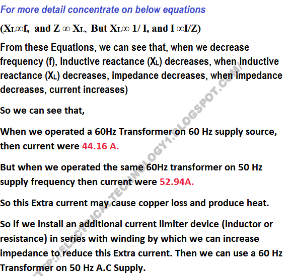
3. What would happen if we operate a 60 Hz Transformer on 50 Hz Source of Supply.(and how can we do that?
- Current will decrease (so increase the current)
- Current will increase ( so decrease the current)
- Current will be same in both cases.
- No Effect ( We can do that without changing anything)
- We can’t perform such an operation.
Show Explanatory Answer
Explanation: Suppose this is a 60 Hz transformer

4. A Step-Up Transformer which has 110/220 turns.What would happen if we replace it with 10/20 turns? (because Turns ratio would be same in both cases)
- induced E.M.F wold be same
- Induced E.M.F would be decreased
Show Explanatory Answer
Explanation:

5. The rating of transformer may be expressed in ____________.
- kW
- kVAR
- kVA
- Horse power.
Show Explanatory Answer
Explanation:
There are two type of losses in a transformer;
1. Copper Losses
2. Iron Losses or Core Losses or Insulation Losses
Copper losses ( I²R )depends on Current which passing through transformer winding while Iron Losses or Core Losses or Insulation Losses depends on Voltage.
That’s why the rating of Transformer is in kVA,Not in kW.
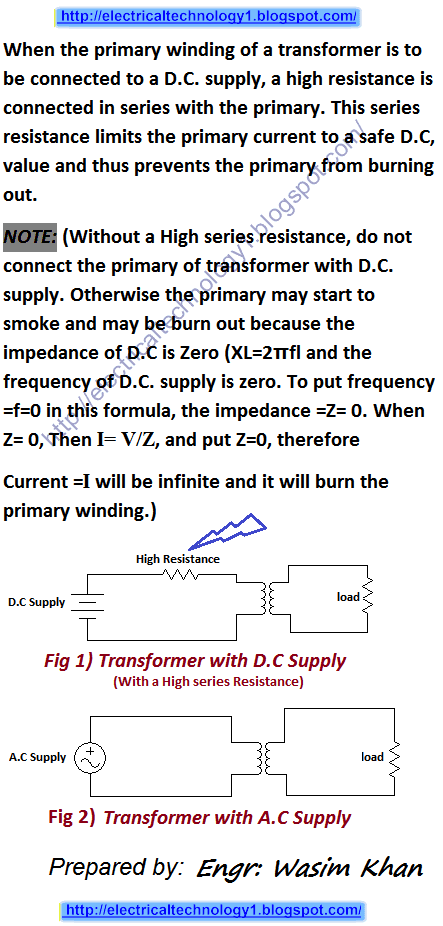
6. What will happen if the primary of a transformer is connected to D.C supply?
- Transformer will operate with low efficiency
- Transformer will operate with high efficiency
- No effect
- Transformer may start to smoke and burn
Show Explanatory Answer
Explanation:

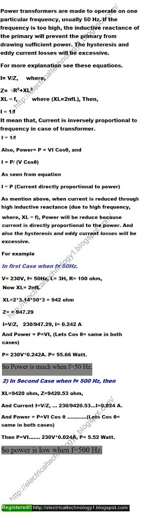
7. What would happen if a power transformer designed for operation on 50 Hz (frequency) were connected to a 500 Hz (frequency) source of the same voltage?
- Current will be too much high
- Transformer may start to smoke and burn
- Eddy Current and Hysteresis loss will be excessive
- No effect
Show Explanatory Answer
Explanation;
8. What would happen if a power transformer designed for operation on 50 Hz (frequency) were connected to a 5 Hz (frequency) source of the same voltage?
- Current will be too much low
- Transformer may start to smoke
- Eddy Current and Hysteresis loss will be excessive
- No effect
Show Explanatory Answer
Explanation:

- Step Up the level of Voltage
- Step down the level of current
- Step up level the power
- Step up the level of Frequency
- 1 and 2 only
Show Explanatory Answer
Explanation:
A Step up transformer only step up the level of voltage and step down the level of current.
because the input power is same.
So according to P=VI→ I = P/V…. We can see that, when Voltage increases, current decreases.
So in Step up transformer, input power is same, therefore, when voltage increases, then current decreases.
10. Under what condition is D.C supply applied safely to the primary of a transformer?
- We can connect directly to DC. No condition required
- We can’t connect to DC Supply
- A High resistance should be connect in series with primary, but circuit will be useless.
- The above statement is wrong
Show Explanatory Answer
Explanation:
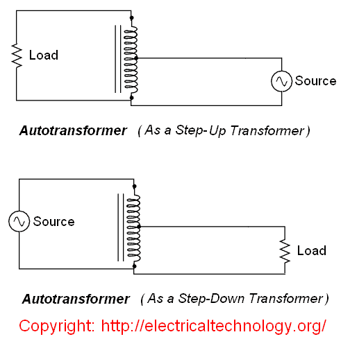
11. An Auto-transformer (which has only one winding) may be used as a ______?
- Step-Up Transformer
- Step-Down Transformer
- Both Step-Up and Step-Down transformer
- None of the above
Show Explanatory Answer
Explanation:
12. E.M.F Equation of the Transformer is _________.
- E1 = 4.44 f N1 Øm , E2=4.44 f N2 Øm
- E1= 4.44 f N1 Bm A , E2 = 4.44 f N2 BmA
- E1= 4.44 N1 Øm/T , E2=4.44 N2 Øm/T
- All of the above
- None of the above
Show Explanatory Answer
Explanation:
Take the basic Equation of the transformer (Option 1) E1 = 4.44 f N1 Øm , E2=4.44 f N2 Øm ,
13. The friction losses in Real Transformers are _________?
- 0%
- 5%
- 25%
- 50%
Show Explanatory Answer
Explanation: Transformer is a Static Devise. So, no rotation, No Friction losses.
14. In Three Phase Transformer, The load Current is 139.1A, and Secondary Voltage is 415V. The Rating of the Transformer would be ___________.
- 50kVA
- 57.72kVA
- 100kVA
- 173kVA
Show Explanatory Answer
Explanation:
Rating of a Three Phase Transformer:
P = √3. V x I
Rating of a Three phase transformer in kVA
kVA = (√3. V x I) /1000
Now
P = √3 x V x I (Secondary voltages x Secondary Current)
P= √3 x 415V x 139.1A = 1.732 x 415V x 139.1A= 99,985 VA = 99.98kVA=100kVA
For more Detail
How to Calculate/Find the Rating of Transformer (Single Phase and Three Phase)?
15 In Single Phase Transformer, The Primary Current and Primary Voltage is 4.55 and 11kV respectively. The Rating of the transformer would be________?
- 50kVA
- 86kVA
- 100kVA
- 150kVA
Show Explanatory Answer
Explanation:
Rating of a Single Phase Transformer:
P = V x I
Rating of a Single phase transformer in kVA
kVA = (V x I) /1000
Now
P = V x I (Primary voltages x Primary Current)
P = 11000V x 4.55A = 50,050VA = 50 kVA
For more Detail .. Read the rating of transformer post in MCQs No 14 explanatory section titled as
“How to Calculate/Find the Rating of Transformer (Single Phase and Three Phase)”?
16. An Isolation Transformer Has Primary to Secondary turns ratio of __________.
- 1 : 2
- 2 : 1
- 1 : 1
- Can be any ratio
Show Explanatory Answer
Explanation: Isolation Transformer is used for isolation purpose only. Isolation transformer transfer electrical power from the source circuit to another circuit with connecting electrically (but magnetically) for preventing electric shock and also used in sensitive devices (like medical equipment etc). Thus, isolation between two electrical circuit can be done by Isolation transformer with turns ratio of 1:1.
17. In an Auto Transformer, The Primary and Secondary are__________Coupled.
- Only Magnetically
- Only Electrically
- Magnetically as well as Electrically
- None of the above
Show Explanatory Answer
Explanation: As we know that in a Transformer, Primary and Secondary winding are magnetically coupled. But in case of Auto transformer, there is only one winding (which is used both as a Primary and Secondary). Thus, in an In an Auto Transformer, The Primary and Secondary are Magnetically as well as Electrically Coupled.
for More detail: Check MCQs No 11 with diagram.
18. A Transformer______________.
- Changes ac to DC
- Changes dc to AC
- Steps up or down DC Voltages & Current
- Steps up or down AC Voltages & Current
Show Explanatory Answer
Explanation: A Transformer does not work on DC and operates only and only on AC, therefore it Step up of Step down the level of AC Voltage or Current.
For More detail: Check MCQs No 9
19. Transformer is a device which:________________.
- Transfer Electrical power from one electrical circuit to another Electrical circuit
- It’s working without changing the frequency
- Work through on electric induction.
- When, both circuits take effect of mutual induction
- Can step up or step down the level of voltage.
- Its Working without changing the Power.
- All of the above
Show Explanatory Answer
20. For a transformer with number of secondary windings more than the number of primary windings, the secondary current will be _____________ ?
- More than the primary current
- Less than the primary current
- Equal to the primary current
- Zero
Show Explanatory Answer
Answer: 2. Less than the primary current
Explanation: For a transformer, ratio of its primary voltage to secondary voltage is equal to ratio of primary turns to secondary turns. Thus, if number of secondary windings is more than number of primary windings, the secondary voltage will also be more than the primary voltage. For a constant impedance coil, current through the coil is inversely proportional to the voltage. Hence, as secondary voltage is higher, secondary current is lower and thus secondary current is less than the primary current.
21. DC power is never applied to transformer
- True
- False
Show Explanatory Answer
Answer: 1, True
Explanatory Answer:
DC voltage applied to the primary of a transformer sets up a constant magnetic flux in its core. Due to absence of any rate of change of flux, there is no induced EMF in the primary to oppose the voltage. Thus, the resistance is very low and current is very high. This high current causes huge heat loss, causing the transformer core to burn and hence, DC power is never applied to transformer.
22. Impedance Ratio of a transformer is equal to _____________.
- Square of turns ratio
- Turns ratio
- 1
- Infinite
Show Explanatory Answer
Answer: 1 .Square of turns ratio
Explanation: For an ideal transformer with no power loss, the output power is equal to input power
i.e., VPIPcosφ = VSIScosφ
cosφ = Power Factor
Therefore, VP/VS = IS/IP = NP/NS
Now, ZP = Primary Impedance = VP/IP
ZS = Secondary Impedance = VS/IS
Thus, ZP/ZS = (VPxIS)/(VSxIP) = (NP/NS)2
23. For a single-phase transformer with 250 primary turns and 50 secondary turns, connected across a 1500 Volts, 50Hz supply, the maximum value of flux is—–
- 1 Wb
- 027Wb
- 04Wb
- 5Wb
Show Explanatory Answer
Answer: 2
For a single-phase transformer, Maximum flux,
Now,
= Primary voltage = 1500 Volts
= Input Frequency = 50Hz
NP = Number of primary turns = 250
Substituting the values, we get, Maximum flux,
![]()
24. For a single phase, 230/2300 Volts, 50Hz core type transformer of cross section 25 cm, if the maximum flux density is 1.12 wb/m2, the number of primary and secondary turns is———–
- 8, 148
- 16, 160
- 23, 230
- 14, 140
Show Explanatory Answer
Answer: 14
Given
Primary Voltage, VP = 230 Volts
Secondary Voltage, Vs = 2300 Volts
Maximum Flux Density, Bmax = 1.12 wb/m2
Area of cross section, A = 0.0625 m2
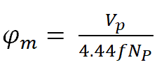
Therefore, Maximum flux, φmax = BmaxA = 0.07 wb
Also, φmax = VP/4.44xfxNP
Where, f = supply frequency = 50 Hz
Thus, NP = 14.8
EMF per turn, E = φmaxx4.44xf = 15.54 V/turn
Thus, number of secondary turns, NS = VS/E = 148
25. For a 300KVA, 11000 Volts/440 Volts, 50Hz single phase transformer, the values of primary and secondary currents are ————–
- 30 Amperes, 750 Amperes
- 2 Amperes, 681.8 Amperes
- 1 Amperes, 752.5 Amperes
- 5 Amperes, 637.5 Amperes
Show Explanatory Answer
Answer: 2
Explanation
Given, Transformer Rating = 300KVA
Primary Voltage = 11000 Volts
Primary Current = Transformer Rating x 1000/Primary Voltage = 27.2 Amperes
Secondary Voltage = 440 Volts
Secondary Current = Transformer Rating x 1000/Secondary Voltage = 681.8 Amperes
26. For a practical transformer at no-load, the input power is equal to the iron losses
- True
- False
Show Explanatory Answer
Answer: 1 True
Explanation
For a practical transformer, if the secondary winding is kept open circuited, it is said to be in no-load condition. As the secondary current is zero, there is no magnetic leakage in the primary and a small current is drawn to supply to the iron losses. Thus, the no load input power is equal to the iron losses.
27. For actual transformers with higher load, leakage flux is prominent
- True
- False
Show Explanatory Answer
Answer: 1
Explanation
In actual transformers, when the primary winding is energized with AC supply, an alternating flux is produced which not only links with the other winding, but also with that winding as well. This is known as leakage flux. At higher loads as primary and secondary currents are higher, the leakage flux is also higher.
28. Which among these losses does not depends on load and is constant?
- Eddy Current Losses
- Hysteresis losses
- A and C
- Copper losses
Show Explanatory Answer
Answer: 3
In an actual transformer, not all of input energy is transferred to output. Rather, a certain amount is lost in the core and as heat. There are two types of losses – Iron and Copper losses. Iron losses are of two types – Eddy Current losses and Hysteresis losses.
Hysteresis loss occurs due to magnetization of atoms in the magnetic material of the core, forming small magnetic domains. This leads to causes huge requirement of energy to power frequent orientation of the magnetic domains in the directions of alternating flux. Since the net hysteresis loss depends upon the maximum magnetic flux density, supply frequency and volume of the core material, it is independent of load and is constant at any load or no load.
Eddy current losses occur due induction of EMF in core laminations which produces circulating eddy currents. These losses also depend upon the magnetic flux density, supply frequency, thickness of laminations and volume of material and are independent of load.
29. For the transformer at no-load, the primary current is 4A at power factor 0.35 and connected across a power supply of 230 Volts, 50Hz, the core loss and magnetizing current are —————-respectively
- 400 W, 2A
- 322 W, 1.4A
- 450 W, 3A
- 433 W, 2.2A
Show Explanatory Answer
Answer: 2
Given:
No load primary voltage, VP = 230 Volts
Supply frequency = 50 Hz
No load primary current, Io = 4 A
Power Factor, cosφ = 0.35
Hence, Iron loss component of no load primary current, IW = Iocosφ = 1.4 A
Magnetizing current component,
![]()
Total Iron losses = VP x Iw = 322 W
30. For the circuit given below along with the parameters, the value of secondary voltage is———–
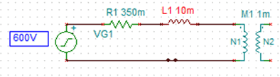
Note: Primary current = 25A
Input Power = 12kW
Transformer Rating = 10kVA, 600V/120V
Supply frequency = 50 Hz
- 100 Volts
- 105 Volts
- 18 Volts
- 8 Volts
Show Explanatory Answer
Answer: ( 3 )
Given:
Primary Voltage, VP = 600V
Power Factor, cosφ = Transformer Rating/ (Primary Voltage x current) = 0.8
Primary reactance, XP = 100πx Inductance = 3.14 Ohms
Primary resistance, RP = 0.35 Ohms
Phase angle, φ = arccos (0.8) = 36.86
Sinφ = 0.6
Primary induced EMF, EP = VP – IPRP cosφ – IPXP sinφ = 600-7-47.1= 545.9Volts
Turns ratio, K = 120/600 = 0.2
Therefore, secondary induced EMF, ES = EP x K = 109.18 Volts
Secondary Voltage, VS = ES = 109.18 Volts
31. For a transformer with ohmic loss of 2% with respect to output voltage and reactance drop of 6% with respect to voltage, the regulation at 0.75 lagging power factor is————
- 5%
- 4.5%
- 6%
- 8%
Show Explanatory Answer
Answer: 2
Given:
Percentage ohmic loss = 2
Percentage reactance drop = 6
Power Factor, cosφ = 0.75
Sinφ = 0.5
Percentage regulation = Percentage ohmic loss x cosφ + Percentage reactance drop x sinφ = 1.5+3 = 4.5%.


i am Arvind garg.i am btech electrical engineer. i want to take knowledge of electrical.
Dear Arvind Garg @ Stay tune to this blog. We update the blog on daily basis. Thanks
A.O.A.
I am a electrical engineer.Your forum is very informative related to electrical.I want ask question related to OP-AMP IC,Why inductors are not fabricated in op-amp IC?Howkind of you!!!!
It is a very useful post. This quiz is very helpful for enhancing basic knowledge. I would like to suggest you to post a quiz related to induction technology. It would be very useful for gaining knowledge about induction technology and its applications.
s ur reply is absoleately correct but i want to know how to see the answer please help any friends
Just click on Show Explanatory Answer
sir, i have a question, If for the given rating and leakage reactance of a three phase transformer if cross section area of core is increased then wat is the effect on the core and copper losses. plz ans thank u sir<br />
i think there will be no change in copper loss but core loss will increase.
i am pursuing btech electrical and want to know about softwares which will help me in future and which r crucial for me…suggest me some..!
i am associate engineer in electrical technology i wana to gain knowledg from u send u r e mail id thx<br />
Which circuit gives by airgap in instrument?
I have a doubt in question no. 4. How could we take the same flux when there are 10 turns. If our input voltage is fixed then we have to find out flux for the particular turns and this flux will be used to determine induced voltage V2. So the induced EMF would be same.<br />
No… You can see the solved example in explanatory answer…practically, we have tried the circuit and the same result obtained as given in explanatory answer.. Thanks.
yes sir i too have the same doubt….when you reduce the turns to maintain the same ratio….the flux is proportional to turns and should decrease according to the turns…simply i want to say that the flux induced due to 110 turns should not be equal to flux induced due to 10 turns…that would violate the law that flux is proportional to no of turns.
Just check again…We can not use 10 turns instead of 110 turns… As EMF is directly proportional to the induced flux and we know that flux is also increases when turn increases.
@ D Chowdhury : Flux established in the core is proportional to the applied voltage. Induced voltage in the winding is proportional to no. of turns and rate of change of flux. So if no. of turns is reduced keeping applied voltage constant the induced voltage reduces.
i have a doubt.the primary flux which is linked to secondary windings via core ,which has some reluctance .therefore the secondary flux is less than primary flux in non ideal case.
Yes! here we talking about ideal case..
Thanks for the information. I found these questions really helpful and interesting which made me to read it again and again. Transformer is an electrical device that makes the transfer of energy by forming inductive coupling between the winding of its circuits. If you are interested in transformer you may visit <a title="Important Questions of Transformer" href="http://blog.oureducation.in/
i have a small dOubt abOut star-Delta cOnnections in tansfOrmer,<br />that Delta-Delta is pOssible or nOt then why they cant be used….
jab tu iss dharti pe possible hai .. toh betta sab kuch possible hai :P
sir<br />we use fuses on the primary side of domestic transformer where 11kv line is connected.<br />but if load is increased on the secondary side of transformer then how these fuse will work which r connected on the primary side.because power on side is same ….plz ans
Fuse wire depends on Current…Not on Power..
very informative knowldge
3 phase transformer main v and i ka phase angle nai lagy ga ?<br />Please tell me ?<br />kya hum ye formula nai laga saqty P=3*v*i* cos pie ?
JazakAllah Kheran
i cant see the answers & explanation , please help me.
We are working on it.. It will be live ASAP. Thanks
Answers are not visible. kindly help.
Click the “Show Explanatory Answer” below each MCQs for Explanatory Answers. let me know if you face any prob. thanks
i also cant see the answer and explanation plzz help me too.
Am B-tech Electrical engineer. Am preparing for interview but I’ve got problem that the answers of transformers MCQs are not showing please check and tell me that the issue is on your side or mine. waiting for quick response.
Dear Muhammad Atif Shehzad @ … Thanks for your feedback… We are working on it…
sir may i request some ebook of TESLA COIL or about wireless energy transmission… thankyou verrymuch in advance… hehe
Vry nice site sir,
I am really impressed
Sir,
In questn no 4, you explained that flux can be calculated through no of turns and input voltage.But as we know the common transformer equation that N1/N2=E1/E2.Through this case this equation is going to be not usefull as the flux is decreased and input voltage is remaining same.In example you have taken input voltage lower then the first so this will in turn reduce flux but we are not decreasing our input voltage so equation must be followed.Please explain this case briefly
Thank you
i find your blog very interesting and useful regarding all the electrical stuff and calculation and relation and wiring have been done perfectly well and good ..
Sir pl explain per unit impedance of transformer and utility of mentioning it in the name plate of a transformer .
The site is so nice
Very nice sir
This all information about transformer is helpful .
nice article