Single Phase AC Circuits MCQs ( With Explanatory Answers)
Single Phase AC Circuits MCQs ( With Explanatory Answers)
1. In case of Inductive circuit, Frequency is ___________Proportional to the inductance (L) or inductive reactance (XL).
- Directly
- Inversely
- No Effect
Show Explanatory Answer
Explanation:
XL =2πfL….. i.e.…. XL∞ f…… and also…..L ∞ f
2. In case of Inductive circuit, Frequency is ___________ Proportional to the Current.
- Directly
- Inversely
- No Effect
Show Explanatory Answer
Explanation:

3. In case of Inductive circuit, inductance (L) is ___________Proportional to the inductive reactance (XL).
- Directly
- Inversely
- No Effect
Show Explanatory Answer
Explanation:
XL =2πfL….. i.e.…. XL∞L.
4. In inductive circuit, when Inductance (L) or inductive reactance (XL) increases, the circuit current decreases, but the circuit power factor ________?
- Increases
- Also Decreases
- Remain Same
- None of the above
Show Explanatory Answer
Answer: 2…Also Decreases
Explanation:
Suppose, when Inductance (L) = 0.02H
V=220, R= 10 Ω, L=0.02 H, f=50Hz.
XL = 2πfL = 2 x 3.1415 x 50 x 0.02 = 6.28 Ω
Z = √ (R2+XL2) = √ (102 + 6.282) = 11.8 Ω
I = V/Z = 220/11.8 = 18.64 A
Cos θ = R/Z = 10/11.05 = 0.85
Now we increases Inductance (L) form 0.02 H to 0.04 H,
V=220, R= 10 Ω, L=0.04 H, f=50Hz.
XL = 2πfL= 2 x 3.1415 x 50 x 0.04 = 12.56 Ω
Z = √ (R2+XL2) = √ (102 + 12.562) = 16.05 Ω
I = V/Z = 220 / 16.05 = 13.70 A
Cos θ = R/Z = 10/16.05 = 0.75
Conclusion:
We can see that, When inductance (L) was 0.02, then circuit current were 18.64 A, and Circuit power factor was (Cos θ) = 0.85.
But, when Circuit inductance increased from 0.02H to 0.04 H, then current decreased from13.70 A to 18.64A, also Power Factor (Cos θ) decreased from 0.85 to 0.75.
Hence proved,
In inductive circuit, when inductive reactance XL increases, the circuit current decreases, but the circuit power factor also Decreases.
5. In inductive circuit, when Inductance (L) or inductive reactance (XL) increases, the circuit current ________?
- Also Increases
- Decreases
- Remain Same
- None of the above
Show Explanatory Answer
Answer:…2…Decreases
We know that, I = V / R,
but in inductive circuit, I = V/XL
So Current in inversely proportional to the Current ( in inductive circuit.
Let’s check with an example..
Suppose, when Inductance (L) = 0.02H
V=220, R= 10 Ω, L=0.02 H, f=50Hz.
XL = 2πfL = 2 x 3.1415 x 50 x 0.02 = 6.28 Ω
Z = √ (R2+XL2) = √ (102 + 6.282) = 11.8 Ω
I = V/Z = 220/11.8 = 18.64 A
Now we increases Inductance (L) form 0.02 H to 0.04 H,
V=220, R= 10 Ω, L=0.04 H, f=50Hz.
XL = 2πfL= 2 x 3.1415 x 50 x 0.04 = 12.56 Ω
Z = √ (R2+XL2) = √ (102 + 12.562) = 16.05 Ω
I = V/Z = 220 / 16.05 = 13.70 A
Conclusion:
We can see that, When inductance (L) was 0.02, then circuit current were 18.64 A,
But, when Circuit inductance increased from 0.02H to 0.04 H, then current decreased from13.70 A to 18.64A.
Hence proved,
In inductive circuit, when inductive reactance XL increases, the circuit current decreases, and Vice Virsa.
6. In case of Capacitive circuit, Frequency is ___________Proportional to the Capacitance (C) or Capacitive reactance (XC).
- Directly
- Inversely
- No Effect
Show Explanatory Answer
Answer: 2. Inversely
Explanation:
In capacitive circuit,
XC= 1/2πfC, and
f = 1/2πXC C
So here we can see that,
f = 1/ C …and also…f = 1/ XC.
So, in a capacitive circuit, frequency is inversely proportional to the Capacitance (C) and Capacitive reactance (Xc)
7. In case of Capacitive circuit, Frequency is ___________ Proportional to the Current.
- Directly
- Inversely
- No Effect
Show Explanatory Answer
Answer: 1 Directly
Explanation:
We know that,
I = V/R
but in capacitive circuit
I = V/Xc……(1)
But we also know that
Xc = 1/2πfC ….(2)….. i.e ….. Xc ∞ 1/f
Puttint (2) into (1)
I = V/ (1/2πfC)…i.e ..I = V x 2πfC
Hence Proved, I ∞ f
8. In case of Capacitive circuit, Capacitance (C) is ___________ Proportional to the Capacitive reactance (XC).
- Directly
- Inversely
- No Effect
Show Explanatory Answer
Answer: 2. Inversely
Explanation:
In capacitive circuit,
XC = 1/2πfC, …i.e,
Xc ∞ 1/C
So, in a capacitive circuit, Capacitance (C) is inversely proportional to the Capacitive reactance (Xc)
9. In a Capacitive circuit, when Capacitance (C) increases, ( the circuit current also increases), then the circuit power factor ________?
- Increases
- Decreases
- Remain Same
- None of the above
Show Explanatory Answer
Answer: 1. Increases.
Explanation:
Suppose, when Capacitance (C) = 500µF = or 5×10-04F
V=220, R= 10 Ω, C=500µF = (5×10-04F), f=50Hz.
XC = 1/2πfC = 1/(2 x 3.1415 x 50 x 5×10-04F) = 6.37 Ω
Z = √ (R2+XC2) = √ (102 + 6.372) = 11.85 Ω
I = V/Z = 220/11.8 = 18.56 A
Cos θ = R/Z = 10/11.85 = 0.84
Now we increased Capacitance (C) = 1000µF = or 1×10⁻³F,
V=220, R= 10 Ω, C=1000µF =1×10⁻³F
XC = 1/2πfC = 1/(2 x 3.1415 x 50 x 1×10-3F) = 3.18 Ω
Z = √ (R2+XC2) = √ (102 + 3.18 2) = 10.49 Ω
I = V/Z = 220/11.8 = 20.97A = 21A
Cos θ = R/Z = 10/11.85 = 0.95
Conclusion:
We can see that, When Capacitance (C) was 500µF, then circuit current were 18.56 A, and Circuit power factor was (Cos θ) = 0.84.
But, when we increased Circuit Capacitance from 500µF to 1000µF, then current also increased from18.56 A to 21A, also Power Factor (Cos θ) increased from 0.84 to 0.95.
Hence proved,
In inductive circuit, when Capacitance C increases, the circuit current also increases, moreover, the circuit power factor also increases.
10. In a Capacitive circuit, when Capacitive reactance increases, then the circuit power factor ________?
- Increases
- Decreases
- Remain Same
- None of the above
Show Explanatory Answer
Answer: 2. Decreases
Explanation:
Suppose, when Capacitive reactance (Xc) = 6 Ω
V=220, R= 10 Ω, Xc = 6 Ω
Z = √ (R2+XC2) = √ (102 + 62) = 11.66 Ω
Cos θ = R/Z = 10/11.66 = 0.85
Now we increased Capacitive reactance = 10 Ω
V=220, R= 10 Ω, Xc = 10 Ω
Z = √ (R2+XC2) = √ (102 + 10 2) = 14.14 Ω
Cos θ = R/Z = 10/14.14 = 0.70
Conclusion:
We can see that, When Capacitive reactance (Xc) = 6 Ω, then circuit power factor was (Cos θ) = 0.85.
But, when we increased Capacitive reactance from 6 Ωto 10 Ω, then Power Factor (Cos θ) decreased from 0.85 to 0.70.
Hence proved,
In Capacitive circuit, when Capacitive reactance (Xc) increases, then the circuit power factor also increases.
11. If Current and Voltage are 90 Degree Out of Phase, Then The Power (P) will be__________.
- Infinite
- Maximum
- Normal
- Minimum
- Zero
Show Explanatory Answer
Answer: 5. Zero
Explanation:If Current and Voltage are 90 Degree Out of Phase, Then The Power (P) will be zero. The reason is that,
We know that Power in AC Circuit
P= V I Cos φ
if angle between current and Voltage are 90 ( φ = 90) Degree. then
Power P = V I Cos ( 90) = 0
[ Note that Cos (90) = 0]
So if you put Cos 90 = 0→Then Power will be Zero
12. In pure inductive circuit, the power is __________?
- Infinite
- Maximum
- Normal
- Minimum
- Zero
Show Explanatory Answer
Answer 5. Zero
Explanation: We know that in Pure inductive circuit, current is lagging by 90 degree from voltage ( in other words, Voltage is leading 90 Degree from current) i.e the pahse difference between current and voltage is 90 degree.
So If Current and Voltage are 90 Degree Out of Phase, Then The Power (P) will be zero. The reason is that,
We know that Power in AC Circuit
P= V I Cos φ
if angle between current and Voltage are 90 ( φ = 90) Degree. then
Power P = V I Cos ( 90) = 0
[ Note that Cos (90) = 0]
So if you put Cos 90 = 0→Then Power will be Zero (In pure Inductive circuit)
13. In pure capacitive circuit, the power is __________?
- Infinite
- Maximum
- Normal
- Minimum
- Zero
Show Explanatory Answer
Answer: 5. Zero
Explanation:
We know that in Pure capacitive circuit, current is leading by 90 degree from voltage ( in other words, Voltage is lagging 90 Degree from current) i.e the phase difference between current and voltage is 90 degree.
So If Current and Voltage are 90 Degree Out of Phase, Then The Power (P) will be zero. The reason is that,
We know that Power in AC Circuit
P= V I Cos φ
if angle between current and Voltage are 90 ( φ = 90) Degree. then
Power P = V I Cos ( 90) = 0
[ Note that Cos (90) = 0]
So if you put Cos 90 = 0→Then Power will be Zero (In pure capacitive circuit)
14. If Power factor = Cos θ = 1, it means that _____________.
- Input = Output
- PIN = POUT
- The circuit is resistive only
- The angle (θ) between Voltage and Current is Zero.
Show Explanatory Answer
Answer: 4. Theangle θ between Voltage and Current is Zero
Explanation: We know that Power factor = Cos θ
Given value of Power factor is = 1.
But, this is only possible when θ = 0 ( in case of Power factor = Cos θ).
I.e, Cosθ = Cos (0) = 1.
15. Using P=VI Cos φ Formula, We Can Find_______.
- Power of Single phase Circuit.
- Voltage of Single Phase Circuit
- Current of Single phase Circuit.
- Power Factor of Single Phase Circuit
- All of the above
- None of the above
Show Explanatory Answer
Answer: 5. All of the above
Explanation: As we know that it depends of the given values or data. but generally we can find all these quantity this way by this formula.
For Power: P=VI Cos φ
For Voltage = V = P / (I Cos φ)
For Current = I = P / (V Cos φ)
For Power Factor = Cos φ = P / VI
16. Reciprocal of Power Factor = _________?
- Q Factor
- Demand Factor
- Diversity Factor
- Utilization Factor
Show Explanatory Answer
Answer: 1. Q Factor
Explanation:
Opposite of Power factor is called the Q-Factor or Quality Factor of a Coil or its figure of merit.
Q Factor = 1/ Power Factor=1/Cosθ= Z/R … (Where Power Factor Cosθ = R/Z)
If R is too small with respect to Reactance
Then Q factor = Z/R = ωL/R = 2πfL / R … (ωL/R = 2πf)
Also Q = 2π (Maximum Energy Stored/Energy dissipate per Cycle) in the coil.
For More Detail : Q Factor in Electrical and Electronics Engineering
17. Power Factor (Cos θ) =_________?
- kW/kVA
- R/Z
- The Cosine of angle between Current and voltage
- All of the above
Show Explanatory Answer
Answer. 4. All of the above.
Explanation:As we know that power in single phase AC Circuits = P = VI Cos θ. Therefore Cos θ = P / V I ===> Cos θ = P (in Watts) / V I (in Volt- Ampere) ===> Cos θ = W/VI .
And Cos θ = R/Z = the ratio between Resistance and Impedance = Resistance / Impedance = R / Z
Also Cos θ = The Cosine of angle between Current and voltage = P = V I Cos θ.
18. The relationship between Impedance (Z) and Admittance(Y) is ___________ ?
- Z=1/Y
- Z=1+Y
- Z=1-Y
- Z=Y2
Show Explanatory Answer
Answer: 1. Z=1/Y
Explanation:
Impedance: The overall resistance in AC Circuit is Called Impedance. It is represented by Z and the unit of impedance is same like resistance i.e. = Ω (Ohm) where is
Impedance = Z =√ ( R2+XL2) …. In case of Inductive Circuit (*XL = Inductive Reactance)
Impedance = Z =√ ( R2+XC2) … in Case if Capacitive Circuit (*Xc = Capacitive Reactance)
Admittance: The Admittance is defined as the reciprocal of impedance just as conductance is the reciprocal of resistance i.e. it is represented by Y.
Admittance,
Y = 1/Z
= 1/ (V/I)
= I/V———> I=VY
The unit of admittance is Siemens and its unit symbol is S.
You may also read about Admittance here
19. Average value of a sinusoidal alternating signal is ————-for a full cycle.
- Maximum
- Zero
- Finite Value
- Infinite
Show Explanatory Answer
Ans: ( 2 )
For a sinusoidal alternating signal, the average value is equal to the steady state value of that electrical parameter which transfers the same change across the circuit as its alternating counterpart. It is determined by averaging all the instant values of the electrical parameter. Since the sinusoidal wave is symmetrical, the average value in the positive cycle would be equal to the average values in the negative cycle. Hence it is zero for a full cycle.
20. The average value of a sinusoidal alternating signal is ————–
- Equal to the maximum value
- Half of the maximum value
- 637 times the maximum value
- None of the above
Show Explanatory Answer
Ans. ( 3 )
Consider the sinusoidal alternating current signal given below.
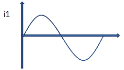
This is a sinusoidal current waveform, where the value of current at any point is given as:
i = Im sinθ
For a small segment of thickness dθ, the area would be: idθ
Integrating for a half cycle, the area would be: ![]()
The average value would be given as : 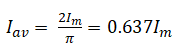
21. Form Factor for a sinusoidal waveform is :
- 1.21
- 0.5
- 1.11
- 0
Show Explanatory Answer
Ans: ( 3 )
The form factor for a sinusoidal waveform is the ratio of its RMS value and its average value. The RMS value is the value of that electrical parameter which would produce the same amount of heat in the circuit its DC counterpart
Mathematically, Form Factor, 
22. Peak Factor for a sinusoidal waveform is:
- 1.3
- 1.02
- 1.14
- 0.5
Show Explanatory Answer
Ans: ( 1.14 )
Peak Factoris the ratio of maximum value to RMS value. It indicates the maximum value.
Mathematically, 
23. Sine Waves of the same frequency can be represented using same phasor
- True
- False
Show Explanatory Answer
Answer: ( 1 )
Phasor Diagram is the representation of a sine wave using a single line rotating in counter-clockwise direction with a constant velocity. While the length of the line represents the magnitude, i.e. the maximum value of the alternating parameter, its orientation with the X-axis represents the frequency. Two sine waves of same frequency would have represented by rotating phasors which maintain a fixed position relative to each other.
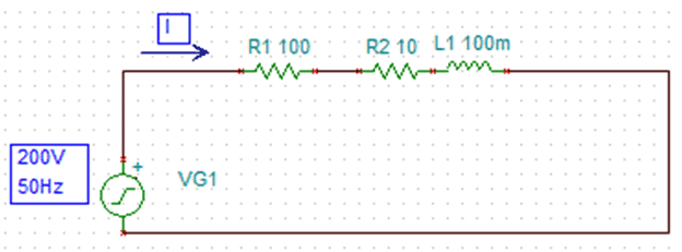
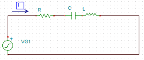
24. For the circuit given below, the approximate value of reactance, impedance, current and power factor is———-respectively.

- 35 Ohms, 90 Ohms, 1 Amperes, 1
- 4 Ohms, 104.8 Ohms, 1.9 Amperes, 0.95
- 40 Ohms, 100 Ohms, 5 Amperes, 0.5
- 50 Ohms, 200 Ohms, 2 Amperes, 0.7
Show Explanatory Answer
Ans. ( 2 )
For the above circuit, the inductive reactance is given as:
The Resistance, R = 100 Ohms
Substituting the values, f = 50 Hz, L = 0.1H, we get = 31.4 Ohms approx.
The impedance is given as:
![]()
Substituting the corresponding values, we get, Z = 104.8 Ohms approx.
The value of current, I = V/Z = 1.9 Amperes
The phase difference is given as: ![]()
Calculating we get, ∅ = 17.43 Degrees
Hence Power Factor, cos∅ = 0.95
25. For the circuit given in previous question, the power consumed is—-
- 200 Watts
- 361 Watts
- 300 Watts
- 500 Watts
Show Explanatory Answer
Answer: ( 2 )
Average power consumed is the power consumed in the resistor, since an ideal inductor does not consumes power. Thus power consumed is given as:
P = VIcos∅
V = Supply Voltage = 200 Volts
Now, from above, I = 1.9 Amperes
Power factor, cos∅ = 0.95
Hence, P = 361 Watts
26. Power Factor for the circuit given below is——–
- 1
- 0.8
- 0.9
- 0.5
Show Explanatory Answer
Ans: ( 2 )
We have the following parameters given
Non-Inductive Resistance, R = 100 Ohms
Inductance of Coil, L = 0.1 H
Resistance of Coil, RL = 10 Ohms
Frequency, f = 50 Hz
Supply Voltage, V = 200 Volts
Inductive Reactance, XL = 2πfl = 31.4 Ohms
Therefore, Impedance of Coil, = 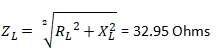
Total Impedance, Z = ZL+ R = 132.95 Ohms
Total current passing through the circuit, I = V/Z = 1.5 Amperes
Now, power factor for only the coil, cosθ = RL/ZL = 0.3
Voltage across coil, VL = IZL = 49.425 Volts
Power Consumed by the coil, PL = VLIcosθ = 22.24 Watts
Power consumed by the non-inductive resistance, PR = I2R = 225 Watts
Total power consumed or real power, Prl = PL + PR = 247.4 Watts
Total input power, PA = VI = 300 Watts
Hence, total power factor, pf = Prl/PA = 0.8
27. For the circuit given in question 6, assume the inductor is replaced by a capacitor of 75 microfarads. The power consumed, maximum charge and maximum energy in the circuit is————respectively
- 300 Watts, 0.1 C, 4 Joules
- 339 Watts, 0.2 C, 3 Joules
- 100 Watts, 0.01C, 12 Joules
- 150 Watts, 0.4 C, 2 Joules
Show Explanatory Answer
Answer: ( 2 )
Similar to an inductor, the power consumed by the capacitor is also zero or almost negligible. Hence for the circuit, the power consumed is the power consumed by the resistance only.
Therefore, power consumed = I2R
Now, I = V/Z
V = Supply Voltage, = 200 Volts
Z = Impedance given as: 
Now, current, I = 1.84 Amperes
Therefore, Power consumed = 338.56 Watts = 339 Watts approx
Maximum charge in the capacitor, Qmax = CVm= CV√2 = 0.02 Columbs
Maximum energy, Emax = 0.5CVm2 = 3 Joules
28. Alternating current across a conductor is ———
- Uniform throughout
- More at the outer surface than at the core
- More at the core than at the outer surface
- Zero at the core
Show Explanatory Answer
Answer:
For a straight conductor, the alternating current produces a magnetic flux, which is more at the centre compared to the surface. This causes inductance to be more at the centre than at the surface. Thus current is more at the outer surface where the inductance is less. Hence useful cross section of the conductor is lesser than the actual one and the effective resistance is higher.
29. For a series RLC circuit at resonance, the voltage drop across capacitive and inductive components is ——-
- Large
- Small
- Zero
- Infinite
Show Explanatory Answer
Answer: ( 1 )
When current across a series RLC circuit is in phase with the supply voltage, it is said to be in resonance. Consider the below series RLC circuit.
Capacitive Reactance = XC = 1/2πfC
Inductive Reactance = XL = 2πfL
Since current is in phase with supply voltage, the total phase difference would be zero and hence XC = XL.
Therefore, impedance, Z = R and current, I = V/Z = V/R
Since opposition to flow of current is only due to the resistor, maximum current flows across the circuit and thus, voltage drop across the capacitive and inductive components is maximum. Thus series resonance is avoided in power systems.
30. Parallel AC systems are used frequently than series AC systems
- True
- False
Show Explanatory Answer
Answer: ( 1 )
Parallel AC systems are used frequently than series AC systems because all the electrical appliances or devices are operated with the same supply voltage and also each one needs to be operated independently using its corresponding switch.


nice one
Thanks Dear
Its very Helpfull… Thanks
Welcome Dear :)
Very good thanks
نور الدين عبد الكريم ابراهيم الحمد<br />Welcome Dear.
question number 7 has been incorrectly interpreted here.<br />we know,<br />I=V/Xc<br />and Xc=1/(2*pi*f*C)<br />that makes f directly proportional to I.
We have correct it. Thanks for review.
Sir please provide other mcqs..
Sir please provide other mcqs like this… other topics
any body can illustrate me question no 4 answer plz in my mind it is like this when inductance increased the power factor of the circuit decreases but here it is inversed……..<br />
Dear..Did you check it properly…???? Try again….
plz provide the answers of MCQs……I cant find them
We are working on it. Thanks for positive feedback.
plz provide the answers of MCQs