What is an Electrical Transformer? Construction, Working, Types and Applications
What is a Transformer? Its Parts, Operation, Types, Limitation & Application
What is a Transformer?
- As the name suggests, an Electrical Transformer transfers electrical power from one electrical circuit to another electrical circuit. It does not change the value of power.
- A Transformer only steps-up or steps-down the level of voltage or current.
- A Transformer doesn’t change the circuit frequency during operation.
- A Transformer works on the principle of electric i.e. mutual induction.
- A Transformer operates when both circuits take effect by mutual induction.
- A Transformer can’t step-up or step-down the level of DC voltage or DC Current.
- A Transformer only step-up or step-down the level of AC voltage or AC Current.
- A Transformer doesn’t change the value of flux.
- A Transformer won’t operate on DC Voltage.
Without transformers the electrical energy generated at generating stations won’t probably be sufficient enough to power up a city. Just imagine that there are no transformers. How many power plants do you think have to be set up in order to power up a city? It’s not easy to set up a power plant. It is expensive.
Numerous power plant have to be set up in order to have sufficient power. Transformers help by amplifying the Transformer output (stepping up or down the level of voltage or current).
When the number of turns of the secondary coil is greater than that of primary coil, such a transformer is known as step up transformer.
Likewise when the number of turns of coil of primary coil is greater than that of secondary transformer, such a transformer is known as step down transformer.
Construction of a Transformer (Parts of a Transformer)
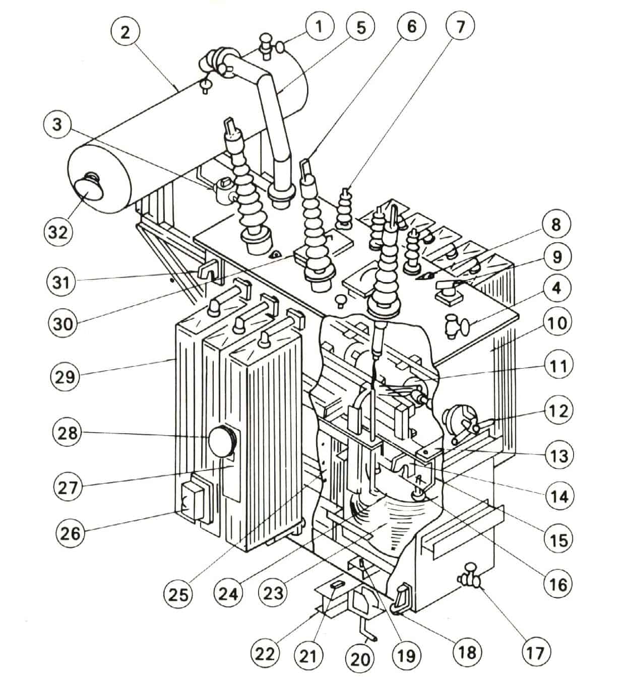
| 1 | Oil filter valve | 17 | Oil drain valve |
| 2 | Conservator | 18 | Jacking boss |
| 3 | Buchholz relay | 19 | Stopper |
| 4 | Oil filter valve | 20 | Foundation bolt |
| 5 | Pressure-relief vent | 21 | Grounding terminal |
| 6 | High-voltage bushing | 22 | Skid base |
| 7 | Low-voltage bushing | 23 | Coil |
| 8 | Suspension lug | 24 | Coil pressure plate |
| 9 | B C T Terminal | 25 | Core |
| 10 | Tank | 26 | Terminal box for protective devices |
| 11 | De-energized tap changer | 27 | Rating plate |
| 12 | Tap changer handle | 28 | Dial thermometer |
| 13 | Fastener for core and coil | 29 | Radiator |
| 14 | Lifting hook for core and coil | 30 | Manhole |
| 15 | End frame | 31 | Lifting hook |
| 16 | Coil pressure bolt | 32 | Dial type oil level gauge |
- Related Post: Open Delta Connections of Transformers
Working Principle of a Transformer
Transformer is a static device (and doesn’t contain on rotating parts, hence no friction losses), which convert electrical power from one circuit to another without changing its frequency. it Step up (or Step down) the level of AC Voltage and Current.
Transformer works on the principle of mutual induction of two coils or Faraday Law’s Of Electromagnetic induction. When current in the primary coil is changed the flux linked to the secondary coil also changes. Consequently an EMF is induced in the secondary coil due to Faraday law’s of electromagnetic induction.
The transformer is based on two principles: first, that an electric current can produce a magnetic field (electromagnetism), and, second that a changing magnetic field within a coil of wire induces a voltage across the ends of the coil (electromagnetic induction). Changing the current in the primary coil changes the magnetic flux that is developed. The changing magnetic flux induces a voltage in the secondary coil.
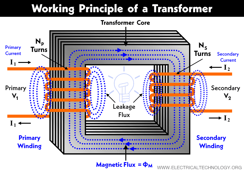
A simple transformer has a soft iron or silicon steel core and windings placed on it(iron core). Both the core and the windings are insulated from each other. The winding connected to the main supply is called the primary and the winding connected to the load circuit is called the secondary.
Winding (coil) connected to higher voltage is known as high voltage winding while the winding connected to low voltage is known as low voltage winding. In case of a step up transformer, the primary coil (winding) is the low voltage winding, the number of turns of the windings of the secondary is more than that of the primary. Vice versa for step down transformer.
Transformer Always rated in kVA instead of kW.
As explained earlier, EMF is induced only by variation of the magnitude of the flux.
When the primary winding is connected to ac mains supply, a current flows through it. Since the winding links with the core, current flowing through the winding will produce an alternating flux in the core. EMF is induced in the secondary coil since the alternating flux links the two windings. The frequency of the induced EMF is the same as that of the flux or the supplied voltage.
By so doing (variation of flux) energy is transferred from the primary coil to the secondary coil by means of electromagnetic induction without the change in the frequency of the voltage supplied to the transformer. During the process, a self induced EMF is produced in the primary coil which opposes the applied voltage. The self induced EMF is known as back EMF.
Ideal Transformer verses Practical Transformer
In our previous post, we have discussed the ideal transformer with phasor and circuit diagrams and detailed comparison with practical transformers. Keep in mind that an ideal transformer has no losses at all e.g. the input power to the transformer is equal to the output power. In addition, it should be noted that ideal transformer is an imaginary (theoretical concept) which does not exist in real life.
Related Posts:
- Difference Between Single Phase and Three Phase Transformer
- Difference Between Ideal and Real or Practical Transformer
Equivalent Circuit of a Transformer
In our explanatory article about equivalent circuit of an electrical Transformer which is a graphical representation of a transformer circuit in which the resistance and leakage reactance are imagined to be external to the winding. The exact equivalent circuit of a transformer can be referred to as the primary side or secondary side.
EMF Equation of a Transformer
Magnitude of the induced EMF (or Voltage) in a transformer can be found by EMF equation of the transformer. When a source of alternating current (AC) is applied to the primary winding of the transformer which is known as magnetizing current, it produces alternating flux in the core of a transformer.
Losses in a Transformer
Unlike an ideal transformer, A real and practical transformer has some losses like ohmic losses, magnetic flux losses, copper and core losses and energy is dissipated in the windings, core, and surrounding structures. Larger transformers are generally more efficient, and those of distribution transformers usually perform better than 98%.
Transformer’s Efficiency
On specific power factor and load, the transformer efficiency and all day efficiency can be found by dividing its output on Input (similar to other electrical machines i.e. motors, generators etc). But the values of both Input and Output should be same in unites (i.e. in Watts, kilowatts, megawatts etc).
Types of Transformers
There are different types of transformer based on their usage, design, construction as follow.
Types of Transformers based on its Phases
- Single Phase Transformer
- Three Phase Transformer
Types of Transformers based on its Core Design
- Core Type Transformer
- Shell Type Transformer
- Berry Type Transformer
Types of Transformers based on its Core
- Air core Transformer
- Ferromagnetic/Iron Core Transformer
Types of Transformer based on its usage
- Large Power Transformer
- Distribution Transformer
- Small Power Transformer
- Sign Lighting Transformer
- Control & Signaling Transformer
- Gaseous Discharge Lamp Transformer
- Bell Ringing Transformer
- Instrument Transformer
- Constant Current Transformer
- Series Transformer for Street Lighting
Related Post: Difference between Power and Distribution Transformers?
Types of Transformer based on Insulation & Cooling
- Self Air Cooled or Dry Type Transformer
- Air Blast-Cooled Dry Type
- Oil Immersed, Self Cooled (OISC) or ONAN (Oil natural, Air natural)
- Oil Immersed, Combination of Self Cooled and Air blast (ONAN)
- Oil Immersed, Water Cooled (OW)
- Oil Immersed, Forced Oil Cooled
- Oil Immersed, Combination of Self Cooled and Water Cooled (ONAN+OW)
- Oil Forced, Air forced Cooled (OFAC)
- Forced Oil, Water Cooled (FOWC)
- Forced Oil, Self Cooled (OFAN)
Types of Instrument Transformer
- Current Transformer
- Potential Transformer
- Constant Current Transformer
- Rotating Core Transformer or Induction regulator
- Autotransformer
Related Post: Power Transformer Protection & Faults
Limitation of the Transformer
To understand the main points, we have to discuss some basic terms related to transformer operation. So lets back to basic for a while.
A transformer is an AC machine that steps up or steps down an alternating voltage or current. A transformer being an AC machine however cannot step up or down a DC voltage or DC current. It sounds a bit weird though. You might be thinking “so are there not DC transformers?”
To answer the two questions whether there are or there are not DC transformers and know “why transformer cannot step up or step down a DC voltage” it’s necessary we know how electric current and magnetic field interact with each other in transformer operation.
Related Posts:
- Maintenance of Transformer – Power Transformers Maintenance, Diagnostic & Monitoring
- Which Transformer is More Efficient When Operates on 50Hz or 60Hz?
- Is it Possible to Operate a 50Hz Transformer on 5Hz or 500Hz Frequency?
Fleming’s Right Hand Rule
It states that “if the thumb, the forefinger and the middle finger are held in such a way that they are mutually perpendicular to each other (makes 90° of Angles), then the forefinger points the direction of the field, the thumb points the direction of motion of the conductor and the middle finger points the direction of the induced Current (from EMF).
Why Transformers Can’t step Up Or Step Down A DC Voltage or Current?
A transformer cannot step up or step down a DC voltage. It is not recommendable to connect a DC supply to a transformer because if a DC rated voltage is applied to the coil (primary) of a transformer, the flux produced in the transformer will not change in its magnitude but rather remain the same and as a result EMF will not be induced in the secondary coil except at the moment of switching on, So the transformer may start to smock and burn because;
In case of DC supply, Frequency is zero. When you apply voltage across a pure inductive circuit, then according to
XL= 2 π f L
Where:
- XL = Inductive Reactance
- L = Inductance
- f = Frequency
if we put frequency = 0, then the overall XL (inductive reactance) would be zero as well.
Now come to the current, I = V / R (and in case of inductive circuit, I = V / XL) …. basic Ohm’s Law
If we put Inductive reactance as 0, then the current would be infinite (Short circuit)…
So, If we apply DC voltage to a pure inductive circuit, The circuit may start to smoke and burn.
Thus transformers are not capable of stepping up or stepping down a DC voltage. Also there will be no self induced EMF in such cases in the primary coil which is only possible with a varying flux linkage to oppose the applied voltage. The resistance of the primary coil is low and as such a heavy current flowing through it will result to the primary coil burning out due to excessive heat produced by the current.
Also read: Under what condition is D.C supply applied safely to the primary of a transformer?
Uses and Application of Transformer
Uses and applications of transformer is discussed already in this previous post.
Advantages of 3-Phase Transformer over 1-Phase Transformer
Read the advantages and disadvantages of Single Phase & three phase transformer here.
Related Posts:
- Parallel Operation of Single-Phase & Three-Phase Transformers
- Transformer Performance & Electrical Parameters
- Transformers Insulation Materials in Oil-Immersed & Dry Type T/F
- Transformers Fire Protection System – Causes, Types & Requirements
- Advantages and Disadvantages of Three Phase Transformer over Single Phase Transformer.
- Transformer Phasing: The Dot Notation and Dot Convention
- Can We Replace a 110/220 Turns Transformer with 10/20 Turns?
- Electrical Transformer Symbols – Single Line Transformer Symbols
- Can We Operate a 60Hz Transformer on 50Hz Supply Source and Vice Versa?
- Sumpner’s Test or Back-to-Back Test on a Transformer
- Open Circuit and Short Circuit Test of a Transformer


What are the dangerous to connect Transformer to the DC power supply. Thanks
Thanks for sharing with us.
It helped me a lot. especially in my assignment.
Excellent article. Keep writing such kind of information. Thanks
Hi there, Please add the selected topics to the transformer. I would be very thankful
Plz, provide information on Transformer tests and ways of cooling.
Nice. Please add more on Transformer regulation and parallel operation. Thanks
That’s why I come to this site regularly and learn lots of new things.
Thanks for the basic information about transformer.
Now, All the basic question about transformer is clear now to me. Thanks
Nice post about Transformer. Thanks for sharing with us.
Touche. Sound arguments. Keep up the great spirit.
how can be increase transformer capacity without changing in construction.
for increase transformer capacity little change must be esential
thanks a lot it’s the good job for us to increase our knowledge
Very good post on transformers, I also have an article regarding types of CTs on my page if anyone is interested in learning more about Current Transformer Theory. Cheers!
wow… awesome write up on transformers. I shall remain ever grateful if this article can be sent to my email address
thanks for the information
Very nice information about transformer i simple language
Thanks
very nice imformations thanks
Hi….which institution in germany can I learn more about transformers as a subject.
Hi….which institution in india can I learn more about transformers as a subject
This is just what i was looking for , straight and simple unlike other definitions we get.
This is genuinely helpful for me. To know every single part and working of Transformer
I try to figured it out… 11kv/415 v transformer. What if… one fuse of one phase open(burn from short) ? We have to phases to primary but what about secondary? The houses/factorys What voltage did they get? Also have 2 phases to secondary? Or we have 3 phases to secondary but all 3 of them with crazy voltages? ? Thanks and keep posting(i print most of your post, im try to make a book) ?
Great explanation of the transformer’s working principle! The detailed breakdown is very helpful. Do you think VR could enhance understanding by allowing students to explore the transformer’s anatomy interactively? Please provide your valuable feedback.