Active, Reactive, Apparent and Complex Power
What is Active, Reactive, Apparent and Complex Power?
What is Active Power: (P)
Active Power is the actual power which is really transferred to the load such as transformer, induction motors, generators etc and dissipated in the circuit.
Alternative words used for Real Power (Actual Power, True Power, Watt-full Power, Useful Power, Real Power, and Active Power) and denoted by (P) and measured in units of Watts (W) i.e. The unit of Real or Active power is Watt where 1W = 1V x 1 A. .
Active Power in DC Circuits:
In DC Circuits, power supply to the DC load is simply the product of Voltage across the load and Current flowing through it i.e., P = V I because in DC Circuits, there is no concept of phase angle between current and voltage. In other words, there is no frequency (f) or Power factor in DC Circuits.
Active Power in AC Circuits:
But the situation in Sinusoidal or AC Circuits is more complex because of phase difference (θ) between Current and Voltage. Therefore average value of power (Real Power) is P = VI Cosθ is in fact supplied to the load.
In AC circuits, When circuit is pure resistive, then the same formula used for power as used in DC as P = V I.
Related Post: Power Formulas in DC, AC Single Phase and and AC Three Phase Circuits.
Active Power Formulas:
- P = V x I (In DC circuits)
- P = V x I x Cosθ (in Single phase AC Circuits)
- P = √3 x VLx IL x Cosθ or (in Three Phase AC Circuits)
- P = 3 x VPh x IPhx Cosθ
- P = √ (S2 – Q2)or
- P =√ (VA2 – VAR2) or
Real or True Power or Active Power = √ (Apparent Power2 – Reactive Power2) or
kW = √ (kVA2 – kVAR2)
Where:
- P = Power in Watts
- V = Voltages in Volts
- I = Current in Amperes
- Cosθ = Power Factor (Phase angle Difference)
- VL = Line Voltage
- IL = Line Current
- S = Apparent Power in VA (Volt Ampere)
- Q = Reactive Power in VAR (Volt Ampere Reactive)
Must Read: Why Transformer Does not Work on DC Supply instead of AC?
What is Reactive Power: (Q)
Also known as (Use-less Power, Watt less Power)
The powers that continuously bounce back and forth between source and load is known as reactive Power (Q)
Power merely absorbed and returned in load due to its reactive properties is referred to as reactive power.
Reactive Power represent that the energy is first stored and then released in the form of magnetic field or electrostatic field in case of inductor and capacitor respectively.
Reactive power is given by Q = V I Sinθ which can be positive (+ve) for inductive loads and negative (-ve) for capacitive load.
The unit of Reactive Power is Volt-Ampere reactive i.e. VAR where 1 VAR = 1V x 1A.
In more simple words, in Inductor or Capacitor, how much magnetic or electric field produced by 1A x 1V is known as the unit of Reactive Power.
- Must read: Is Reactive Power Useful?
Reactive Power Formulas:
- Q = V I Sinθ
- Reactive Power = √ (Apparent Power2– True power2)
- VAR = √ (VA2 – P2)
- kVAR = √ (kVA2 – kW2)
Where:
- θ = Phase angle
What is Apparent Power: (S)
The Product of voltage and current if and only if the phase angle differences between current and voltage are ignored.
Total power in an AC circuit, both dissipated and absorbed/returned is referred to as apparent power
The combination of reactive power and true power is called apparent power
In an AC circuit, the product of the r.m.s voltage and the r.m.s current is called apparent power which is denoted by (S) and measured in units of Volt-amp (VA).
It is the product of Voltage and Current without phase angle.
The unit of Apparent power (S) VA i.e. 1VA = 1V x 1A.
When the circuit is pure resistive, then apparent power is equal to real or true power, but in inductive or capacitive circuit, (when Reactances exist) then apparent power is greater than real or true power.
Apparent Power Formulas:
- S = V I
- S = √ (P + Q2)
- Apparent Power = √ (True power2 + Reactive Power2)
- kVA = √kW2 + kVAR2
What is Complex Power ? (S = P+jQ or S=VI*)
The Complex sum of Real Power (P) and Reactive Power (Q) is known as Complex Power which can be expressed like S = P+jQ and measured in terms of Volt Amps Reactive (generally in kVAR).
It may also be expressed as S=VI* where “I*” is the conjugate of the complex current I. This current “I” flows through a reactive load Z caused by the Voltage.
Complex Power Formulas:
Complex Power in Capacitive Loads
- Z = R – jXC
- I = IP + jIQ
- Cosθ = R / |Z| (leading)
- I* = IP – jIQ
- S = P – jQ
A Capacitive Load provide Leading VARS (i.e. it eliminates VARS and improves the overall power factor of the system). That’s why capacitors are used to correct and improve the power factor.
Complex Power in Inductive Loads
- Z = R + jXL
- I = IP – jIQ
- Cosθ = R / |Z| (lagging)
- I* = IP + jIQ
- S = P + jQ
Where:
- Z = Impedance
- R = Resistance
- XL = Inductive Reactance
- XC = Capacitive Reactance
- Cosθ = Power Factor
- P = Active Power
- S = Apparent Power
- Q = Reactive Power
An Inductive Load provide lagging VARS (i.e. it added VARS and decrease the overall power factor.)
Complex power can also be expressed by the following formula.
Resistor absorbs the real power and dissipates in the form of heat and light. Inductor absorbs the reactive power and dissipates in the form of magnetic field Capacitor absorbs the reactive power and dissipates in the form of electric or electrostatic filed
Good to know:
Power Triangle
∴ Active, Reactive, Apparent Power and Power factor are trigonometrically related to each other as shown in below figure (Power Triangle).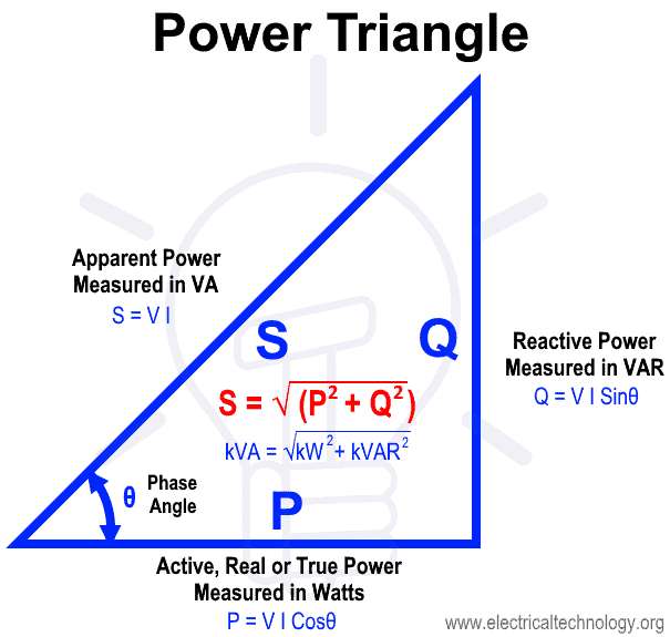
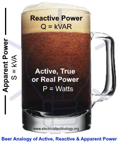
For easy explanation, all the related quantities can be easily understand by the funny Lays Chips and Beer Analogy for Real or True or Active Power, Reactive Power , Apparent Power and power factor.

Role of Active Power and Reactive Power
There is an important relationship between active and reactive power and the post below will help to understand that why active power (P) is called true power and reactive power (Q) is called imaginary power. Explanations given in this article are rarely available in the books.
First understand what is a coil and inductor. Take an iron rod, wrapped (i.e. winding) it with copper wire. It is a coil or you can say inductor, electromagnet etc. If current passes through the copper wire then iron rod gets magnetized. More will be the current, more the magnetism in the iron rod (i.e. more the flux in iron rod & more the magnetic field around it). Or, it can be said that more the current, more the energy stored by the inductor. (Energy stored by the inductor is given by ![]() where ‘L’ is the inductance of inductor and ‘I’ is the magnitude of current through the inductor).
where ‘L’ is the inductance of inductor and ‘I’ is the magnitude of current through the inductor).
(1) Now consider the following R-L circuit as shown on Figure-1. All the value of current and voltage are also shown in the Figure.

Active power consumed by the circuit is I2R = 222x6 = 2904 Watt. What is the meaning of this power? Please note that “Watt= Joule/second”. Therefore it means that resistor in the circuit is consuming 2904 Joule energy per second and dissipating it in the air. It is not storing any energy. So you can say it is the true power, or actual power which is used. (If you will keep your finger near the resistor, you will find it hot, because it is dissipating energy in the air, i.e. electrical energy is converted into thermal energy).
Now what about inductor?
It is an AC Circuit, current is changing continuously. Therefore in the first quarter cycle inductor consumes energy, because current is increasing (energy stored by the inductor is ![]() In next quarter cycle, energy is released by the inductor because there is a decrease in current. In next quarter cycle (third quarter) current is increasing (in reverse direction), so again energy is stored by the inductor. In next quarter cycle (fourth quarter) current is decreased, so, again energy is released by the inductor. This procedure is explained in Figure-2.
In next quarter cycle, energy is released by the inductor because there is a decrease in current. In next quarter cycle (third quarter) current is increasing (in reverse direction), so again energy is stored by the inductor. In next quarter cycle (fourth quarter) current is decreased, so, again energy is released by the inductor. This procedure is explained in Figure-2.
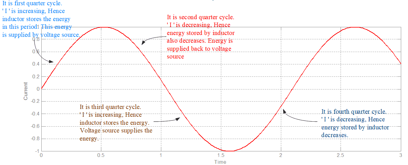
So, inductor is consuming energy in a quarter cycle (taking it from voltage source) and giving back energy in next quarter cycle to the voltage source or you can say it is exchanging energy with the voltage source. In this case, it can be said that Inductor is consuming reactive power and voltage source is generating the reactive power. But note that it is an energy exchange between voltage source and inductor. There is no power consumed by inductor. This is the reason reactive power is called imaginary power.
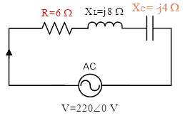
(2) Now take another example. Consider following RLC circuit (Figure-3):

In this circuit, value of inductive reactance and capacitive reactance is same. If you will calculate Power Factor (PF) of this circuit, then you will find it unity. Energy stored by the inductor is ![]() as written earlier. Energy stored by a capacitor is given by
as written earlier. Energy stored by a capacitor is given by ![]() (V is magnitude of voltage across capacitor; here onward it will be denoted by ‘Vc’). In AC circuit both ‘I’ and ‘Vc’ are changing continuously. If you will draw the wave form of current ‘I’ and ‘Vc’ then you will find that when ‘I’ is increasing at the same time ‘Vc’ is decreasing and vice-versa. It implies that in a particular quarter cycle if inductor is storing the energy, at the same time capacitor is releasing the energy. In next quarter cycle reverse will happen, i.e. capacitor will store the energy and inductor will release the energy. So, there is an energy exchange continuously between inductor & capacitor.
(V is magnitude of voltage across capacitor; here onward it will be denoted by ‘Vc’). In AC circuit both ‘I’ and ‘Vc’ are changing continuously. If you will draw the wave form of current ‘I’ and ‘Vc’ then you will find that when ‘I’ is increasing at the same time ‘Vc’ is decreasing and vice-versa. It implies that in a particular quarter cycle if inductor is storing the energy, at the same time capacitor is releasing the energy. In next quarter cycle reverse will happen, i.e. capacitor will store the energy and inductor will release the energy. So, there is an energy exchange continuously between inductor & capacitor.
It is called:
Inductor consumes reactive power and capacitor generates reactive power.
But it is an energy exchange between two elements. No true power is consumed or generated; this is the reason reactive power (Q) is called imaginary power.
Note that:
- Inductor consumes reactive power and capacitor generates reactive power. It is the conventions made by Scholars of Electrical Engineering. Reactive power is imaginary power; neither it is consumed nor can be generated.
- In power system, most of the loads are inductive load (induction motors, coils etc.), due to this reason, the convention ‘reactive power is consumed by inductor’ is developed.
- In power system, to calculate complex power, formula S=VI* is used instead of S=V*I. It is because to allocate plus sign to reactive power consumption to inductors/coils/induction motors etc.
(3) Now consider the following circuit (Figure 4):
Now you can understand easily that in this case half of the total reactive power consumed by inductor will be supplied by voltage source and half reactive power will be supplied by capacitor. (It implies that inductor will exchange the energy both with voltage source and capacitor).
Consider the circuit diagram shown in Figure-5:
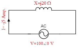
Value of current shown in the figure can be verified by the readers, it is –j5 A. If one ammeter is inserted in the circuit, what will be its reading? Its reading will be 5 Amp., while no true power is consumed by circuit. So, for the purpose of energy exchange, between voltage source and inductor, current flows in the circuit. You can understand that inductor is consuming reactive power (imaginary power), no true power is consumed despite that flow of current is necessary. If wattmeter is inserted in this circuit (current coil in series with voltage source and pressure coil across voltage source), its reading can be found to be zero.
You can understand concepts of active power & reactive power with one more example. Consider Figure-6:

It has one synchronous generator (alternator) supplying power to induction motor with 3Ø line. Synchronous generator is taking 20 KW Mechanical input (through steam supply), its total losses are 2 KW and electrical output is 18 KW. 2 KW losses means, 2KJ energy per second is dissipating in the air; or we can say electrical energy is converted into the thermal energy (this is the reason you can find generator, transformer, motor etc. hot in running condition). Synchronous generator is supplying 10 KVAR reactive power, but it can be seen that to generate reactive power, no mechanical input is required. Induction motor is consuming 10 KVAR reactive power (because induction motor has coils, so it has inductive nature)*. With the figure-6, you can understand synchronous generator is generating reactive power (if running at high DC excitation) and induction motor is consuming reactive power, but in fact it is just an energy exchange between generator and induction motor.
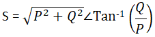
Suppose a transformer is inserted in Figure-6, between synchronous generator & induction motor, what will be the load on transformer? Answer is 20.59 KVA. It can be calculated as
![]()
The exact explanation is, To exchange the energy between synchronous generator & induction motor (i.e. to supply reactive power by the generator), flow of current is necessary (as explained through Figure-5); So load on transformer is just not active power, it is combination of active & reactive power. Of course, active & reactive power cannot be simply added. Their addition follows the equation:
![]()
Rating of Voltage Controller at Your Home:
In your house, suppose you have an air-conditioner, having consumption of 2 kW power. You may require a stabilizer (voltage controller) with this. Stabilizer is just a transformer. Stabilizer should be installed between voltage supply and the air-conditioner. What may be the rating of stabilizer? Rating of stabilizer maybe around 4 KVA. The reason is that air-conditioner consumes reactive power also (it has a motor inside it). So, the kVA rating of stabilizer is certainly more than 2 kVA. Though the reactive power is imaginary power i.e. exchange of energy between air-conditioner and voltage supply but for this exchange of energy, current flows between air-conditioner and stabilizer, that passes through the winding of stabilizer (transformer), therefore just a 2 kVA stabilizer is not sufficient.
In most of the countries, the meters installed in residential areas are KW-Hr meter; so you have to pay electricity bill of active power; reactive power is free; but any transformer or voltage controller is to be installed accommodates reactive power also, hence rated in kVA (apparent power). Therefore in aforesaid example, a consumer has to pay bill of 2 kW power (as it is true power), reactive power is free (as it is imaginary power), but while installing any transformer or voltage controller, reactive power cannot be ignored.
Note a few more important points:
- Induction motor always runs at lagging power factor as it always consumes reactive power along with active power.
- Synchronous generator can run at leading, lagging or unity Power factor. Synchronous generator is a generator, so it always supply active power, but if running on low excitation, it consumes reactive power, in this condition it can be said it is running at leading PF.
- Synchronous generator shown in figure-6 is running at lagging Power factor
- It is a common question of students, if synchronous generator is generating reactive power, how you have termed it as lagging Power factor. The reason is that suppose induction motor terminal voltage is 1∠0pu and current consumed by it is 0.9∠-30°pu. It is lagging current, so, we can say motor is running under lagging PF. Same current is supplied by generator & same is terminal voltage of generator, hence relation between terminal voltage of generator and current supplied by it is lagging, hence its PF of generator is also lagging.
Or, simply if direction of P & Q is same it is lagging PF. If direction of P & Q is opposite it is leading PF.
* You can ask Synchronous motor also has coils, it has no capacitor inside it, how it can generate reactive power. The answer is that it has field winding, which can increase the flux in the synchronous motor. The induction motor has no field winding.
- By: Electrical Techology
- Updated By: Dr. Vipin Jain Ph.D in Electrical Engineering
Related Posts:
- What is Electrical Power? Types of Electric Power and their Units
- Power Factor
- Causes of low Power Factor
- Advantages of Power factor improvement and Correction
- Disadvantages of Low Power Factor
- Power Factor improvement Methods with Their advantages & Disadvantages
- How to Calculate the Suitable Capacitor Size in Farads & kVAR for Power factor Improvement
- How to Convert Capacitor Farads into kVAR and Vice Versa (For Power factor improvement)
- CAPACITOR BANKS – CHARACTERISTICS AND APPLICATIONS
- Analysis of Reactive Power in Power System


The analogy with the beers and the chips are simply awesome!!!! specially the one with the beers. Can I use the beer image for one of my presentations? how can I get this image? thanks in advance.<br />
You are Welcome dear
why electrical engineering is much more complex than other technologies
Bcz it use more thinking and application
thank alot .complex power explain .pls
Awesome
The beer and chip diagrams are deceptive. They imply True Power and Reactive Power when added together are Apparent Power. It does not. It is the the square of true power and the square of reactive power which equals the square of apparent power.
It’s Vector Addition…
Actually u people made electrical is very easy…hatsoff to all ur people efforts…once upon a time i was very confused about this subject..but by d grace of allah nw all my confusion was gone…if i go good position in my carrier one of d credit goes to u people also..thanks a lot..keep it up..
No this is very simple farmula but using to mind so all heard also question simple but some solution these are hord, I can do this question but all people some many help me…?
Please help me to understand s=vi* i am seeing this in many places. Why we are putting * near current. I know it is conjugate but I want to know what is the need for that
same confusion if got answer plz cnfrm me
Please help me to understand s=vi* i am seeing this in many places. Why we are putting * near current. I know it is conjugate but I want to know what is the need for that
plz say me in uae all use std for power factor pf=0.9….? can yu explain me properly
how can i compute for values of R,L, and C in an AC circuit
pls help active power and reactive power
Article is really awesome and full of information. You can also see information about active reactive and apparent power here.
Explanation with lays example is really awesome..it helped me a lot thank you
Thanks,
Really very simple to understand. thanks a lot
book. Q. c,r,r
Very good writer
Practical commentary . I am thankful for the insight ! Does anyone know where I can get ahold of a template UK VT79 form to fill in ?
awesome explanation ……. it helps us to understand very well and also help to .. remember in future …thanks
Can I use this in star and delta to fund out real ,apprentice and reactive power
IF S is known than how can we calculate values of R and Q ????
This is the most simple explanation! The beer and chips example is very humorous and it cleared my doubts! Thanks.
HHHHHHHHHHHH I like the LAYS example it represents the reality
How does a negative power factor look when it is graphed? How will this impact apparent power versus true power versus reactive power? And how do we interpret this as per power dissipated versus power absorbed/returned to the system?
Quote; Inductor absorbs the reactive power and dissipates in the form of magnetic field”
Absolutely disagree with this statement.
Inductors absorbs real power ( Kinetic Energy) in the form of a magnetic field then dissipates in the form of reactive potential. this reactive potential is then a completely separate energy quanta not being associated with the original energy quanta that created the field in the first place.
I think both statements are true cos inductors are just coils in a motor or an alternator/generator and they perform opposite functions……
It is such a useful explanation of basics of electrical engineering.Thank you very much sir…