Can We Operate a 60Hz Transformer on 50Hz Supply Source and Vice Versa?
What Happens When a 50Hz Transformer Operates on 60Hz and Vice Versa?
Let’s suppose we have a transformer with same rating and parameters when operated at 60Hz and 50Hz supply frequency then. Lets see what happens.
Transformer Rating & Parameters
Suppose, a transformer rating as follow where we will connect it first to the 60Hz supply frequency and 50Hz later.
- V = Voltage = 5kV
- R = Resistance = 6.1Ω
- L = Inductance = 0.3 Henry
- f = Frequency = 60Hz
Transformer Operated on 60Hz
To find the current in the primary of transformer by using I = V / Z, so we will first find the impedance which depends on inductive reactance.
Inductive Reactance = XL = 2πfL
XL = 2πfL = 2 x 3.1415 x 60 x 0.3 = 113.1 Ω
And
Impedance Z = √ (R2+XL2)
Z = √ (6.12+113.12)
Z = 113.26 Ω
Now the value of current
I = V / Z
I = 5kV / 113.26 Ω
I = 44.14 A
Transformer Operated on 50Hz
The same transformer is now connected to the 50Hz frequency. We will do the same calculation as above for 60Hz transformer.
Inductive Reactance = XL = 2πfL
XL = 2πfL = 2 x 3.1415 x 50 x 0.3 = 94.245 Ω
And
Impedance = Z = √ (R2 + XL2)
Z = √ (6.12 + 94.245 2)
Z = 94.44 Ω
Now the value of current
I = V / Z
I = 5kV / 94.44 Ω
I = 52.94 A
We see that the value of primary current in case of 50Hz transformer is more than in case of 60Hz transformer.
Now the more current, the more problems i.e.
- XL ∝ f
- Z ∝ XL
But
- XL ∝ 1/I
And
- I ∝ I/Z
In simple words:
- When frequency (f) increases, Inductive reactance (XL) increases.
- When Inductive reactance (XL) increases, Impedance (Z) increases.
- When Impedance Increase, Current decreases.
So we can say that:
When we operate a 60Hz transformer on 60Hz supply source, the current were 44.14 A.
But when operated a 60Hz transformer on 50Hz supply source, the current were 52.94 A.
The extra current in this case may causes copper loss (P = I2R) and produces heat.
We may use an additional current limiter device (Inductor or resistor) in series with the primary winding of a transformer by which we can increase the overall impedance to reduce the extra current. This way, we can use a 60Hz transformer on 50Hz AC Supply.
If we still able to operate a 50Hz transformer on 60Hz, we may face the following results.
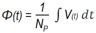
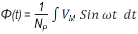
The applied voltage to the primary of transformer windings
V(t) = VM Sin ωt … Volts
is applied to a transformer’s primary winding, the flux of the transformer is given by
If the applied voltage V is increased by 10%, the resulting maximum flux in the clore also increases by 10%.
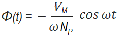
The 10% increase in flux requires an increase in magnetization current much larger than 10% (see fig 1). As the voltage increase, the high magnetization current soon becomes unacceptable. The maximum applied voltage and rated voltage is set by the maximum acceptable magnetization current in the core. Keep in mind that voltage and frequency are inversely proportional (i.e. V 1/f) when the value of maximum flux is constant.
ΦMax = – VM / ωNP
Where
- ΦMax = Maximum flux
- VM = Max voltage
- NP = Number of turns in primary
- ω = 2πf ( where f = frequency)
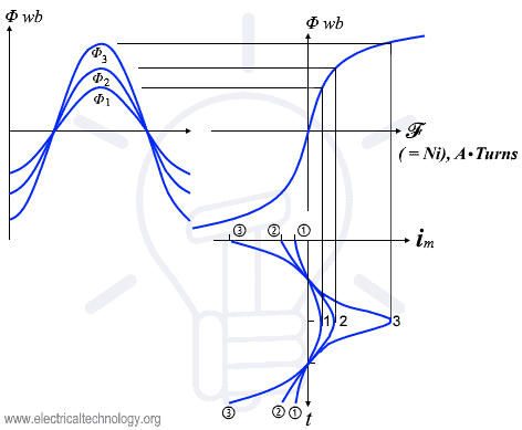
Therefore, if a 60Hz transformer is to be operated on 50Hz, its applied voltage must also be reduced by 1/6 or the peak flux in the core will be too high/. This reduction in applied voltage with frequency is known as derating.
Similarly, a 50Hz transformer may be operated at a 20% higher voltage on 60Hz if this action does not cause insulation problems.
Related Posts:
- Can We Replace a 110/220 Turns Transformer with 10/20 Turns?
- Why Transformer Does not Work on DC Supply instead of AC?
- Why Current Increases When Capacitance Increases or Capacitive Reactance Decreases?
- Why Current Decreases When Inductance or Inductive Reactance Increases?
- In a Capacitive Circuit, Why the Current Increases When Frequency Increases?
- In an Inductive Circuit, Why the Current Increases When Frequency Decreases?
- Why Power Factor Decreases When Inductance or Inductive Reactance Increases?
- Why Power Factor Decreases When Capacitive Reactance Increases or Capacitance Decreases?


Thanks for the PRATICAL TUTORIAL.
It depends upon the margin of safety in the design. The lower the frequency, the higher the flux density at a given voltage. Inverse proportionality frequency means 60/50 = 20% higher flux density. When you pass the knee of the saturation curve characterizing the material, the excitation current and core losses of the transformer dramatically increase and voltage clips. Margins are generally 10% on voltage ratings. If it doesn’t say 50Hz and you can’t lower input voltage by at least 10%, don’t push your luck.
Hi
Why magnetic field always associated with current?
Why electrostatic field always associated with voltage?
I need in depth scientific analysis.