Electric Phase or AC Line Tester – Construction and Working
Electric Phase Tester – Construction and Operations of AC Mains Tester
What is an Electric Phase Tester?
An electric phase tester (also known as a mains tester, line tester, or phase tester) is a basic contact voltage detector tool used to test and identify the phase (also known as live, line, or hot) wire or conductor in an electrical installation. There are multiple Contact Voltage Testers and Non-contact voltage testers (NCVTs) and detector available in the market. They are also referred to as AC voltage or current detectors or Neon Line or Neon Lamp Testers.
Good to Know:
- An AC contact phase tester doesn’t detect DC supply, but only detects AC supply.
- A phase or line tester is also called a neon screwdriver or test pin.
- There are mu
- Phase, line, hot, and live are terms used for a wire or conductor with high potential, e.g., 230V or 120V. In this case, the phase (hot) has 230V or 120V while the neutral wire has 0V AC.
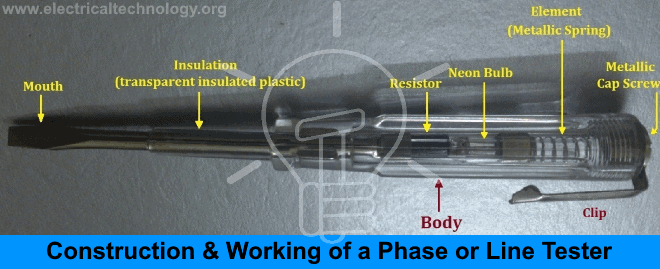
Construction of Phase or Line Tester
Following are the main parts of a typical phase or line tester.
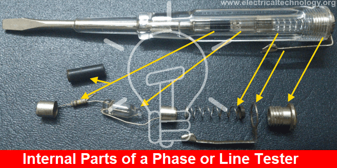
1. Metallic Rod and Tip
It is a cylindrical metal rod. The flat end (mouth) is used as a screwdriver or to touch electrical conductors/wires to find phase or live wires. The other end is connected to the resistor, neon bulb, element, and metallic cap screw respectively. The flat end of the cylindrical metal rod is also covered with transparent insulated plastic for insulation purposes except at the mouth.
2. Body and Insulation
All components (resistor, neon bulb, element or metallic spring, and metallic cap screw) are covered in a transparent insulated body made of plastic. The flat end of the cylindrical metal rod is also covered with transparent insulated plastic for insulation purposes except at the mouth.
3. Resistor
A resistor is an element that opposes the flow of current through it. In a phase or line tester, the resistor is connected between the cylindrical metal rod and the neon bulb to prevent high current and reduce it to a safe value to protect the neon bulb.. The main function of this resistor is to reduce the high AC voltage (230V or 120V) to the safe level up to 80V for the neon bulb. Without a resistor, high current may damage the neon bulb and may cause serious injury.
4. Neon Bulb
The neon bulb is connected between the resistor and the element (metallic spring). The striking voltage needed to ionize the gas inside the glass chamber is 80V. It is used as a phase indicator bulb. When a small current flows through it, the neon bulb starts to glow. Due to the neon bulb, a phase or line tester is also called a neon screwdriver.
5. Element (Metallic Spring)
The element (metallic spring) is used to make a connection between the neon bulb and the metallic cap screw.
6. Metallic Cap Screw and Clip
The metallic cap screw is used to secure all the components inside the phase tester slot. Additionally, the metallic cap screw is connected to the spring (element), which is then connected to the neon bulb. The clip is used for holding the phase tester in a pocket.
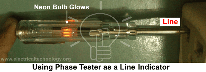
Working of a Phase or Line Tester
When an operator touches the mouth (flat end of the metallic rod) of the phase or line tester with a live/hot wire while one of his /her fingers touches the metallic cap screw or clip of the phase/line tester, the circuit is completed, and a very small amount of current starts to flow in the metallic rod, causing the neon bulb inside the mains tester to glow.

The metallic rod is connected to the resistor, which reduces the high current and voltage to a safe value. The resistor decreases the value of supply voltage from 230V or 120V to the 80V which is enough to lite up the neon bulb inside the electric tester. The reduced current passes through the neon bulb, which is connected to the metallic spring. The metallic spring is connected to the metallic cap screw, which is in contact with our fingers.
The body of operator acts as a Neutral where the neutral is grounded to the earth either at transformer or substation. Hence, a very small current passes through our body to the earth, completing the circuit.
When the circuit is completed, current starts to flow, and the filament of the neon bulb starts glowing. This indicates that the touched wire with the phase/line tester mouth is phase/line/hot.
A phase tester, also known as a mains tester or neon screwdriver, is a simple and effective tool for this purpose. Follow these steps to use a phase tester to identify the live conductor:
- Safety First: Ensure you are wearing appropriate personal protective equipment (PPE) such as insulated gloves and safety goggles. Make sure the area around you is dry to avoid any accidental electric shocks.
- Check the Tester: Before using the phase tester, verify that it is functioning correctly. You can do this by testing it on a known live circuit. If the neon bulb inside the tester glows when touching the live wire, the tester is working properly.
- Expose the Conductors: Carefully expose the conductors in the circuit. Make sure the wires are separated and not touching each other or any conductive surfaces.
- Testing the Conductors:
- Live Conductor Identification: Touch the metallic tip of the phase tester to one of the conductors while holding the insulated handle. Ensure your finger is in contact with the metallic cap or clip of the tester.
- Observation: Observe the neon bulb inside the tester. If the neon bulb glows, the conductor you are testing is the live conductor. If it does not glow, the conductor is either neutral or the circuit is not live.
- Repeat for All Conductors: Repeat the testing process for all exposed conductors in the circuit to identify the live one.
- Verify: After identifying the live conductor, verify your findings by retesting to ensure accuracy.
- Turn On the Power: If you had turned off the power, you can now safely turn it back on, ensuring all conductors are properly insulated and secured.
- Mark the Live Conductor: Once identified, mark the live conductor with appropriate labeling or color coding to avoid confusion in future tests or repairs.
If the same action is performed and the neon bulb does not glow, it means that it is either ground or neutral wire/conductor, or there is no mains supply in the phase wire, or the phase wire is broken in the middle.
FAQs
- What is an electric phase tester?
An electric phase tester, also known as a mains tester or neon screwdriver, is a tool used to identify the live (phase) wire in an electrical circuit.
- What are other names for an electric phase tester?
It is also known as a mains tester, line tester, or neon screwdriver.
- What is the primary use of a phase tester?
The primary use is to detect the presence of voltage in a wire, helping to identify live (hot) conductors in electrical installations.
- How do I use a phase tester to identify a live conductor?
- Touch the metallic tip of the tester to the wire.
- Ensure your finger is in contact with the metallic cap or clip of the tester.
- Observe if the neon bulb inside the tester glows.
- What should I check before using the tester?
Verify the tester’s functionality on a known live circuit to ensure the neon bulb glows.
- Can I use a phase tester on both AC and DC circuits?
Phase testers are primarily designed for AC circuits and may not work on DC circuits due to the lack of neutral and insufficient voltage to light the neon bulb.
- How does a phase tester work?
When the tester’s metallic tip contacts a live wire and the user’s finger touches the metallic cap, a small current flows through the user to the ground, causing the neon bulb to glow.
- What components are inside a phase tester?
A typical phase tester contains a metallic rod, a resistor, a neon bulb, a metallic spring, and a metallic cap screw within a transparent insulated body.
- What is the role of the resistor inside the tester?
The resistor reduces the high current to a safe value to protect the neon bulb and the user.
- Why is the neon bulb not glowing when I test a wire?
- The wire may not be live (it could be neutral or disconnected).
- The phase tester might be faulty.
- Insufficient contact between the tester and the wire.
- What should I do if the tester doesn’t work on a known live circuit?
- Ensure your finger is in contact with the metallic cap.
- Check the tester for damage or replace it.
- Why does the neon bulb glow dimly?
This could indicate a weak connection or lower voltage in the wire being tested.
- Can I use a phase tester in wet conditions?
No, always use the tester in dry conditions to avoid the risk of electric shock.
- Is it safe to touch the conductor if the phase tester doesn’t show the live supply?
No, it is not safe to touch the conductor even if the phase tester does not show a live supply. There may be a fault in the tester or the wire may still carry a dangerous voltage. Always use proper safety precautions and verify with multiple methods.
- Can I use the electric tester with high voltage? If no, what is the safe limit?
No, it is not safe to use the electric tester with high voltage. The safe limit for most phase testers is typically within 100V to 500V. Always check the manufacturer’s specifications for the safe operating range.
- Is it safe to rely solely on a phase tester for all electrical work?
While phase testers are useful for identifying live wires, they should be used alongside other tools and safety practices for comprehensive electrical work.
Safety Precautions
- Never Touch Live Wires Directly. Always use the phase tester to identify live conductors and avoid direct contact. Do not touch open wires or conductors even if the tester shows the absence of phase or hot supply.
- Use the Tester Correctly. Ensure you are holding the insulated handle and touching the metallic cap as per the tester’s design.
- Test in a Controlled Environment. Avoid using the tester in wet or damp conditions to reduce the risk of electric shock.
- Never work on electricity without proper guidance and care.
- Use the line tester only with 100V-500VAC.
- Do not use the phase or line tester with high voltages.
- Do not hit the handle of the line tester; otherwise, the neon bulb or element may be damaged.
- Doing your own electrical work is dangerous and illegal in some areas. Contact a licensed electrician or the power supply company before making any changes to electrical wiring connections.
- Electricity is hazardous. If you give it a chance to harm you, it will not miss it. Please read all cautions and instructions carefully while performing this tutorial practically.
- Follow Manufacturer’s Instructions. Adhere to the specific instructions and guidelines provided by the phase tester manufacturer.
- The author will not be liable for any losses, injuries, or damages from the display or use of this information or if you try any circuit incorrectly. So please, be careful because it’s all about electricity, and electricity is very dangerous.
Related Posts:
- Basic Electrical Engineering Tools, Devices and Their Uses
- All About Electrical Protection Systems, Devices And Units
- How to Test a Capacitor? 8 Ways to Check a Capacitor.
- How to Test a Diode using Digital & Analog Multimeters
- How to Test a Transistor using Multimeter – 4 Ways
- How to test a battery using Test meter?


It is a cylindrical metal rod. The flat end (mouth) is used as a screw driver or touch electrical conductors/wires to find phase or live wires and the other end is connected to the resistance.
thank you sir for your blog about neon tester
am so much excited after reading your blog. Your blog is very much innovative and much helpful for any industry as well as for person.High Voltage Testing
what if , when tester comes in contact with DC,It glows or not , if Glows then why it is so.;
Dear sirs.I read one of u r article about Line tester with nice details.Easily we can understand how it works, what r all its inside parts etc in a simple&legible way. Tnx for it..Now I request u to kindly send one WIRING DIAGRAM of a ROTARY swtch of 4 ;points suitable for a Philips Mixie grinder motor wires of 3 speed with one incher switch&Overload connection&line indicator etc.After changing the line indicator bulb I am confused of fixing the power&motor winding wires in the rotary switch.my mixie is Philips 230Volts A.c -600 watts3 speed rotary switch ith incher switch&line indicator.Kindly send me correct wiring diagram for switch&motor wires&powerchord etc by my email given above..tnx chandran(Retd Engineer)28-1-15one yellow wire.one green wire.one black wire are seen from motor to rotary switch….
Thanks for appreciation… We Will post it as soon as possible.
One of my small tablefan PRIYA without capacitor&Oscillations run nicely but getting heated soon though working.How to prevent getting heated the fan for running continuously without getting heated220V an single phase induction motor only with 5 leafs of plastic just like”WILSSON” etc Delhi make.Plz advice soon by my email as I am a regular reader in email of u r articles. Thanks (ACN)14-10-16
electrical line tester
can anyone tell me that how the current path gets completed while standing o a wooden Floor.????
wood still is slightly conductive
What is the value of resistor???
we rgetting useful day to day electrical technology information in a simple&lucid manner by email.Tnanks (acn)
Want line tester raw material
what if we have no contact with earth, or we are standing on a very good insulating material?
will the glow get reduced when testing low voltage??
What is the maximum voltage that this type of tester can detect?
I always use this one.
Professional and honest Electrician Ocala FL—great experience from start to finish.