How to Determine the Right Size Capacity of a Subpanel?
Sizing the Suitable Capacity of a Subpanel or Main Lug
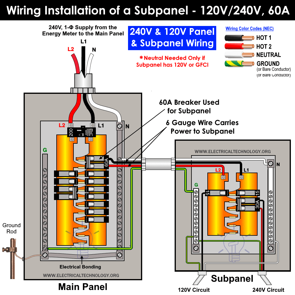
A subpanel or main lug (also known as a remote panel in the NEC) is a smaller service panel installed downstream from the main breaker box or load center in a home. Typically, a subpanel is installed in a separate section of a property, such as a barn, garage, workshop, or another part of a building for specific applications.
When wiring a subpanel or main lug, it is important to calculate the suitable size of the subpanel based on the specific load points. The rated capacity of the subpanel should not exceed the peak amount of power used by the electrical appliances and other connected load points, such as outlets and receptacles.
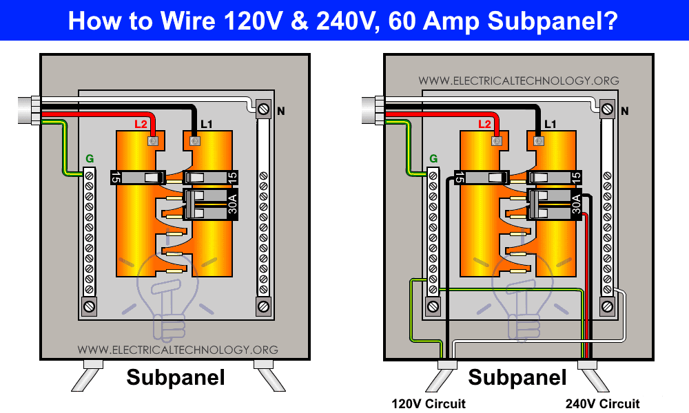
The subpanel is wired to the main panel through a feeder using two hot wires (Hot 1 and Hot 2), connected to a 240V two-pole breaker, and a ground wire. The neutral in the subpanel is only required when there are 120V circuits, GFCI/AFCI outlets, or breakers, in addition to 240V circuits. Note that bonding in the subpanel is not required because the ground and neutral are already bonded and grounded in the main service panel.
The purpose of both the main panel and the subpanel is the same: they distribute the power, control and protect the wired circuits against electrical faults, electric shocks, and surges. A subpanel is mainly used to provide electricity via additional circuit spaces and separate power control management and protection for the circuits.
Related Posts:
- How to Size a Load Center, Panelboard and Distribution Board?
- How to Determine the Number of Circuit Breakers in a Panelboard?
How to Size a Subpanel or Main Lug?
For load calculation, multiply continuous loads (lasting 3 or more hours, e.g., water heaters) by 125% per NEC 310-14 and add 100% of non-continuous loads (like light bulbs, TVs).
Total Load = 125% * Continuous Loads + 100% * Non-Continuous Loads
To account for the fact that all loads are unlikely to operate simultaneously, NEC 220.110 and Table 220.42 recommend applying a demand factor. The first 3 kVA is rated at 100%, while the remaining non-continuous load is rated at 35%.
For example, with a total load of 24,000 watts, the demand factor reduces it to 10.35 kW.
3 kW (100% * 24 kW) + 7.35 kW (35% * (24 kW – 3 kW)) = 10.35 kW
For more details, refer to NEC sections 220.110, 220.14, 220.42, 220.45, 220.53, 220.55, and 517.22.
Let’s follow the example below to determine the appropriate subpanel capacity and number of circuit spaces:
Example:
Suppose we need to install a subpanel for three circuits having total load of 8,540 watts for both 120V and 240V circuits with the following ratings:
- General Lighting = 120V, 1500 W
- 1 x Outlets : 120V x 12A = 1440 W
- 1 x Electric heater: 240V x 23.3A = 5600 W
Solution:
Typically, general lighting and smaller appliances are connected to 15A or 20A, 120V single-pole breakers. Larger appliances, such as air conditioners, water heaters, and electric ranges, are connected to 20A to 50A, 240V double-pole breakers.
Calculating the Wattage
To find the appropriate subpanel rating, we must first calculate the total wattage of the appliances that will be connected to the subpanel or main lug:
1500 W + 1440 W + 5600 W = 8540 W
Calculating the Amperes
Next, we calculate the amperage rating of the appliances. Since the voltage levels are 120V and 240V (in the US), we use the higher voltage level, 240V, for calculation:
I = P ÷ V
Where:
Substitute the values:
I = 8540 W ÷ 240V
I = 35.6A
Applying a Safety Factor
To ensure proper and smooth operation of circuit breakers in high-temperature conditions, apply a safety factor of 125% (1.25) to the calculated amperage. The NEC suggests that the OCPD devices should be able to handle up to 125% of the load current. This complies with NEC 310.14, 705.12(B)(3), 210.19(A) 220.12-16 and 310.15.
125% × 35.5A = 44.48A
Future Expansion
To allow for future expansion and more breakers and circuits in the empty slots, it is recommended to add 20% to the calculated amperage:
20% × 44.48A = 53.38A
Based on this estimate, the next available and suitable size main switch breaker for the subpanel is 60A.
NEC 310.15(B)(16) suggests that a 6 AWG wire is the appropriate feeder size for a 60A subpanel. If the distance exceeds 140 feet (42 meters), use a 4 AWG wire instead of 6 AWG. For the ground wire, use #8 AWG.
Related Posts:
- How to Wire a Subpanel? Main Lug Installation for 120V/240V
- How to Find the Proper Size of Circuit Breaker? Breaker Calculator & Examples
Subpanel Space and Circuits
The example above for given load requires three breakers: two 1-pole, 120V breakers and one, 2-pole, 240V breaker, occupying four spaces.
Therefore, a minimum 4-space, 8-circuit main lug is necessary. For future expansion, a 6-space, 12-circuit subpanel is recommended for a 60A setup designed for an 8.5kW load.
Related Posts:
- How to Find The Suitable Size of Cable & Wire ? – Solved Examples
- What is the Right Wire Size for 15A Breaker and Outlet?
- What is the Suitable Wire Size for 20A Breaker and Outlet?
- How to Find Voltage & Ampere Rating of Switch, Plug, Outlet & Receptacle
- How to Wire a Single Element Water Heater and Thermostat?
- Wire & Cable Size Calculator in AWG
- Electrical Wire & Cable Size Calculator (Copper & Aluminum)
- How to Wire Single-Phase, 230V Consumer Unit with RCD? IEC, UK & EU
- How to Wire a Garage Consumer Unit?
- How to Wire 120V & 240V Main Panel? Breaker Box Installation
- How to Wire 277V & 480V, 1-Phase & 3-Phase, Commercial Main Service Panel?


