Calculation of Sag in Overhead Transmission Lines
What is Sag?
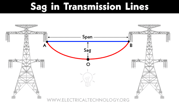
Sag in overhead power transmission line refers to the natural, downward curvature or dip that occurs in the power lines between support structures, such as utility poles or towers, due to the influence of gravity.
This curvature is a result of the cable’s weight and tension and is designed to keep the lines at a safe distance from the ground and other objects while allowing for thermal expansion and contraction. Sag in transmission lines is carefully calculated and controlled to ensure the lines maintain their appropriate height above the ground.
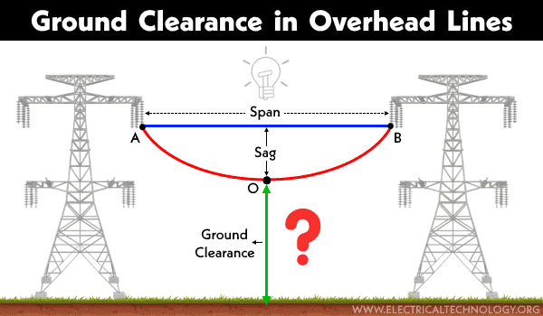
As shown in the fig below, sag is the difference in level between two points “A and B”, and the lowest point “O” of the conductor on a support structure, such as a tower or pole. It is represented by the symbol of “S”. Where the span is the distance between two support structures, such as utility poles or transmission towers towers.
Related Posts:
- What is the Minimum Ground Clearance for Overhead Power Line?
- Why are Overhead Power Lines Loose on Electric Poles & Towers?
Good to Know:
The sag and stresses of line conductors change in response to temperature fluctuations due to thermal expansion and contraction.
-
When the temperature increases (due to excessive sunlight), the length of the conductor expands, resulting in an increase in sag.
-
When the temperature decreases (due to snowfall and ice coating around the conductor), the length of the conductor contracts, leading to an increase in tension, which reduces the sag.
Calculation of Sag in Power Lines
When Supports are at Equal Level
Suppose a conductor is suspended between two supports, A and B, at equal heights, with the lowest point of the conductor marked as ‘O’. It can be proven that the lowest point of the conductor is located at the midpoint of the span, which means it will be in the middle of the total length of the conductor.
Suppose,
- The length between two support towers = span = L meter
- Conductor’s weight per unit length = W kg/m.
- Tension in conductor = T kg
We have designated a point ‘P’ on the conductor and taken the lowest point of the conductor, ‘O,’ as the center. Let’s assume the coordinates of point ‘P’ are X and y. Now, let’s consider a scenario where the curvature (length) is so small that the curved length is equal to the horizontal projection.

OP = x
The two forces applied on OP part of the conductor are:
- Weight of conductor (W.x) applied on x/2 at a distance from point “O”.
- Tension (T) applied on point “O”.
Solving for the moments of both forces applied on point “O”.

The maximum sag “S” on support A or B can be represented by “y“.
Suppose, S = y and x = L/2, then;
Sag on support A:

When Supports are at Unequal Level
In mountainous regions, conductors are typically installed on rugged supports at varying heights. Let’s consider a scenario where a power line conductor is hanged between two supports, “A” and “B”, with point “O” being the lowest point of the hanging line.
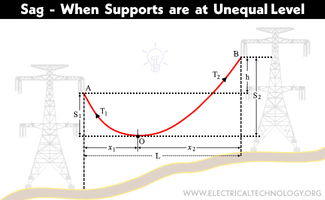
- Length of Span = L meter
- Difference between the level of supports (height) = h meter
- Distance from Support A to O = x1 meter
- Distance from Support B to O = x2 meter
- Tension in conductor = T kg
If the weight per unit length of conductor = W, then;

We know that;

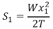
Suppose, x = x1 and y = S1, then;
Sag S1 on Support A:
Sag S2 on Support B:

It is clear from the fig that;
x1 + x2 = L … (Equation 1)
The difference in height (h) between S1 and S2;

We know that S1 – S2 = h, therefore;

Solving equations 1 and 2, we get;

The above calculations and formulas are applicable only under ambient temperature conditions, without considering ice coating and wind pressure on the conductor.
Effect of Wind and Ice on Sag
The effects of ice and wind pressure on conductors in power lines can be significant and potentially detrimental. Here are some key points:
- Increased Weight: When ice accumulates on power line conductors, it adds weight to the lines. The weight of the ice can cause the conductors to sag, potentially leading to a reduction in the vertical clearance between the conductors and the ground, structures, or vegetation.
- Increased Mechanical Stress: Wind pressure, especially during strong storms, exerts forces on the conductors. The combination of ice and wind pressure can lead to increased mechanical stress on the conductors, poles, and towers. This stress can compromise the structural integrity of the power line components.
- Sag and Tension Changes: Ice accumulation and wind pressure can alter the sag of conductors, affecting their tension. This can lead to undesirable effects such as conductor breakage, especially if the conductor tension exceeds safe limits.
- Icing-Related Outages: Accumulated ice on conductors can cause power outages by increasing the likelihood of conductor failure or causing short circuits. Ice can also damage insulators and associated components.
Sag Calculation in the Presence of Ice and Wind Pressure

Total weight of conductor per unit length
Wt = √(Wc + Wi)2 + (Ww)2
Where:
- Wc = weight of conductor per unit length
- Wi = weight of ice per unit length
- Ww = Wind force per unit length
Density of Ice:
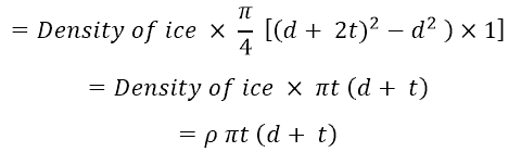
Where:
- d = diameter of the conductor
- t = Thickness of the ice coating around the conductor
Wind Pressure (P):
Ww = wind force per unit length
= wind pressure per unit area × projected area per unit length

When both the wind pressure and ice coating are there on the conductor then:
- Conductor will vertically maintain itself at θ angle which can be calculated using the following formula.

- The sag in conductor can be determined by using the following formula

- Vertical sag in the conductor
SV = S Cos θ
Why is Sag Mandatory in Transmission Line Conductors?
Sag is mandatory in transmission line conductors for several important reasons:
- Safety: Sag ensures that transmission lines remain at a safe distance from the ground, structures, and vegetation. This helps to prevent accidents and electrical hazards, ensuring the overhead lines protection as well as people and property.
- Prevents Overheating: Sag allows for thermal expansion and contraction of the conductors as they heat up and cool down. This helps to dissipate heat and prevents overheating, which can damage the conductors and lead to power outages.
- Reduces Tension: The controlled amount of sag reduces tension in the conductors. This is particularly important during temperature fluctuations and high winds, as excessive tension can lead to conductor breakage.
- Maintains Electrical Clearances: Proper sag ensures that the conductors maintain appropriate electrical clearances from the ground, nearby objects, and other conductors, preventing short circuits and electrical faults.
-
Resists Dynamic Loads: Sag helps the conductors withstand dynamic loads, such as those caused by wind and ice, without experiencing excessive mechanical stress.
Related Posts:
- Skin Effect and Factors Affecting Skin Effect in Power Lines
- Ferranti Effect – Causes, Advantages & Disadvantages
Disadvantages of Loos Sage in Power Lines
The demerits of having excessive or loose sag in power lines include:
Reduced Ground Clearance: Loose sag can lead to a decrease in the vertical ground clearance between the conductors and the ground and structures. This can increase the risk of electrical arcing, fires, and potential safety hazards.
Loss of Mechanical Strength: Excessive sag can put undue stress on the conductors and the supporting structures, leading to mechanical weaknesses and an increased risk of structural failure.
Conductor Damage: Loose sag may cause the conductors to swing or sway, increasing the chances of conductor-to-conductor or conductor-to-object contact. This can lead to conductor damage, short circuits, and power outages.
Safety Hazards: Loose sag can pose safety hazards to people and property. It can create a risk of electrical shocks, fires, and other accidents.
Loss of Efficiency: When conductors are not properly tensioned, it can result in increased line losses due to higher resistance in the power transmission system. This can reduce the overall efficiency of the power distribution network.
Wind and Ice Impact: Loose sag can make power lines more vulnerable to the impact of strong winds and ice accumulation. This can lead to conductor damage, breakages, and service disruptions during adverse weather conditions.
Aesthetic Concerns: Loose sag can lead to an unsightly appearance of power lines, which may not be well-received by the community or local authorities.
In short, the loose sag in overhead transmission lines has the following impacts on the power system.
- Tall poles and towers are required for installation.
- Strong foundations are necessary for structures (towers).
- The cost of installation increases with the size of the supporting structure.
- Strong and heavy cross arms are needed for installation.
- More conductor material is required due to the increased wire length.
- The weight of the conductor also increases.
- Additional insulator strings are needed for installation.
- There is an increase in vibrations.
- Unequal spacing between conductors increases the risk of collisions during a storm.
Related Posts
- Skin Effect and Factors Affecting Skin Effect in Power Lines
- Ferranti Effect in Power Lines – Causes, Advantages & Disadvantages
- Corona Effect & Discharge in Transmission Lines & Power System
- Types of Insulators used in Power Transmission and Overhead Lines
- Classification of Electric Power Distribution Network Systems
- Types of Insulators used in Power Transmission and Overhead Lines
- Classification of Electric Power Distribution Network Systems
- Electric Power System – Generation, Transmission & Distribution of Electricity
- What is the Purpose of Ground Wire in Overhead Transmission Lines?
- Why is the Grounding Wire Bare and Not Insulated?
- Why Don’t Birds and Squirrels Get Electrocuted on Power Lines?
- Why are Overhead Power Transmission Lines Not Insulated?
- How Many Poles and Towers are Situated Within a 1-km Span?
- Why is the Ground Wire Always Positioned Above the Overhead Power Lines?
- What are the Effects of Temperature on Sag in Overhead Lines?
-
 What is the Right Wire Size for a 30A Breaker and Outlet?
-
 The Mini LineFly Drone Robot Saves Birds from Colliding with Power Lines
-
 What is the Correct Wire Size for 25A Breaker and Load?
-
 What is the Suitable Wire Size for 20A Breaker and Outlet?
-
 What is the Right Wire Size for 15A Breaker and Outlet?
-
 How to Install NEMA 14-50R, 50 Amp Heavy Duty EV Outlets?