How to Reverse a Photo Eye Circuit for 120V-277V AC and 12-24V DC Load Circuits using ST01 Timer?
As the ordinary dusk-dawn or photo eye night light circuit works such a way where it turns ON the load at the night and switch OFF in the morning. In today’s wiring tutorial, we will learn how to reverse the photo eye circuit so that 120V and 24V AC/DC load turns ON during the day instead of night and vice versa.
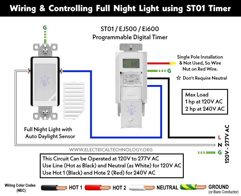
Let’s see the following ordinary photo-eye circuit where a 120V-277V AC full-night light with an auto daylight sensor is additionally controlled by a digital programmable timer (ST01, EJ500, Ei600, etc.).
As the light sensor (which can be fixed in a normal switch box) automatically turns ON and OFF during night and day, respectively, the additional programmable timer can be used to override/delay the night light operation (e.g., if you want to turn off the light 4 hours later than the default setting for dusk).
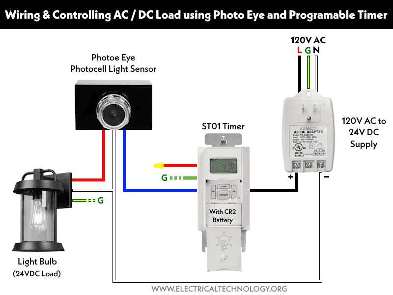
A similar circuit is shown below for a 24V DC load, where the timer is connected to a 120V to 24V DC adapter. The same purpose is applied, i.e., for a dusk-dawn control circuit.
Related Posts:
- How to Wire Twin Timer with Photo Eye Circuit for Time Delay?
- How to Wire ST01 Timer for Dusk-Dawn On-Delay Light Control?
Now, we want to reverse the circuit operation from dusk-dawn to dawn-dusk. Let’s see how to do it.
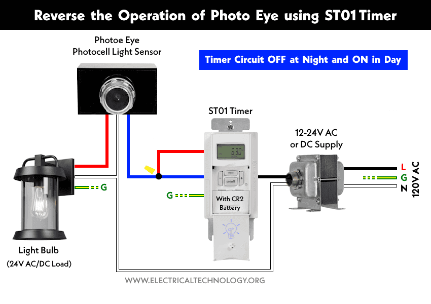
In the following circuit, a 24V AC or DC night light bulb (in the hallway or outdoors) is controlled by both a photo eye (photocell light sensor) and an ST01 timer.
In normal operation, the light will turn ON in the evening and turn off automatically in the morning. You may have noticed the red wire in the timer is capped off (a wire nut is put on it).
Now, if you want to reverse the operation of the circuit, simply wire the Blue and Red wires together from the timer and connect it to the photo-eye (as shown in the figure). Now the circuit is reversed; for example, the light will turn OFF at night and switch ON in the sunshine (during the day).
Good to know: it is recommended to add a relay or contactor if the load (for example, motors, water heater etc.) exceeds 4 amps at 120V AC or 2 amp at DC.
Rating and Features of Digital Programmable Timer
- They are dusk-dawn and dawn-dusk timers and, like a photo-eye, can be used for both AC and DC circuits.
- Ei600 and ST01 timers have a built-in CR2 battery (long life, ranging from 2 to 5 years). Therefore, they don’t need an external 120V supply and a neutral wire.
- These digital programmable timers can be used for 6-24V DC circuits.
- The ST01 can be wired for 2A at 28 VDC and 4A for 12 VDC.
- The ST01 can be wired for 6A at 120V/208V/277V.
- For motor loads, it can be wired for 1 hp at 120V and 2 hp at 240V.
- For resistive loads, it can be wired up to 20A at 120-277VAC. For ballast, 16A at 120V AC is the safest limit.
- The Intermatic ST01 timer automatically adjusts for the time zone.
- They are adjustable for slightly longer or shorter dusk-dawn operations.
- For dusk to dawn, cap off (put a wire nut) on the red wire and connect the blue wire to the load.
- For dawn to dusk, connect the red wire and blue wire together and connect them to the load point.
Related Posts:
- How to Wire ON-Delay Timer for 120V and 240V Load Circuits?
- How to Wire OFF-Delay Timer for 120V and 240V Load Circuits?
- How to Wire AH3 OFF-Delay Timer and Relay with Boiler Fan?
- How to Wire Remote Control Countdown Timer?
- Difference Between ON Delay and OFF Delay Timer
- How to Wire ON/OFF Delay Timer for AC & DC Loads – 230V & 24VDC
- Automatic & Manual Control of 3-Phase Motor Using Delay Timer
- Wiring of DOL Starter for Automatic / Manual Control Using Digital Timer
- Automatic ON/OFF Circuit Using Two 8-PIN Timers for 1 & 3-Φ Load

 How to Wire a 30A, 125V/250V – NEMA 14-30 Receptacle
 How to Wire a 20A, 125V/250V – NEMA 14-20 Receptacle
 How to Wire NEMA TT-30 Receptacle for RVs & Travel Trailers
 How to Wire a 50A – 250V, NEMA 6-50 Receptacle
 How to Wire a 30A – 250V, NEMA 6-30 Receptacle
 How to Wire a 50A – 125V – NEMA 5-50 Receptacle