Wiring Remote Control Countdown ON/OFF Delay Timer
Remote control countdown timers are versatile devices used in various applications, from lighting control to home automation and industrial processes. They allow you to set specific time intervals for turning on or off electrical devices remotely, providing convenience and energy-saving benefits. In this article, we will walk you through the process of wiring a remote control countdown timer (such as Woods 32555WD & TB/PA 318 etc.) for ON and OFF Delay operations, enabling you to effectively manage your electrical devices with precision.
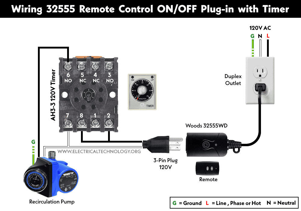
How to Wire 32555 Remote Control Plug-in with Timer?
In the following wiring diagram, we have used the Woods 32555WD wireless remote control plug-in with the AH3 timer to control the automatic ON and OFF operation of a recirculation pump.
As shown in the wiring circuit, the 32555 countdown timer is wired to a duplex outlet via a 120V AC supply. The 8-pin AH3-3 timer and the recirculation pump are connected via a three-pin plug inserted into the remote outlet.
This setup allows you to remotely control the ON-delay or OFF-delay operation of a circuit, such as a recirculation pump for hot water in the bathroom, or any other LED and CFL lighting points, etc.
- The ON/OFF Delay time can be specified in the AH3 timer by rotating the knob to the specific time frame.
- The wireless remote control grounded outlet can be wired for 120V, 8A, and a maximum of 1000 Watts.
- In the case of tungsten and similar load types, the maximum load rating is 650 Watts at 6A and 120V.
- The maximum range of operation for remote control is 100ft (30.5m).
How to Wire TB & PA-318 Wireless Countdown Timer?
In the following wiring circuit, we have used the TB-318 transmitter and the Skylink PA-318 receiver as a remote Plug-in ON/OFF control for a delay mechanism.
As shown in the figure, the PA-318 plug-in ON/OFF control receiver is wired to a duplex outlet via a 120V AC supply. The TB-318 wall switch remote transmitter is also used to wirelessly control the ON and OFF operations of the circuit.
A load point is connected to the grounded outlet of the PA-318 receiver via a 3-pin plug. To configure the circuit, let’s consider the following features before wiring the load points.
- It can be used as ON/OFF control or countdown timer to delay the circuit operations.
- The rating of max load for PA-318 is 1500 watts at 12.5A and 120V AC.
- The max of 1/3hp (minimum 10W) inductive (such as motor) load can be connected to the transmitter.
- It can be wired to control the delay from 1 minute to 60 minuets.
- The max range of operation for remote control is 500ft (152m).
Countdown Timer Operation:
When the circuit is activated by providing the input signal to the receiver, the load will be switched on for a specified timeframe (set up in the device, e.g., from 1 up to 60 minutes). When the delay time expires, the circuit will turn off to save energy. This mechanism is known as OFF-Delay operation of the circuit.
When the load circuit is operational in the ON/OFF mode, press and hold the “SET” button, and the RED LED will start flashing. The number of blinks indicates the timer setting in minutes, e.g.
| Number of Blinking | Timer Duration (In Mins) |
| 1 | 1 |
| 2 | 5 |
| 3 | 15 |
| 4 | 30 |
| 5 | 60 |
ON/OFF Operation:
In this mode, the circuit will be switch ON or OFF when a proper input signal is received by the receiver from transmitter or other sources.
Related Posts:
- How to Wire ON-Delay Timer for 120V and 240V Load Circuits?
- How to Wire OFF-Delay Timer for 120V and 240V Load Circuits?
- How to Wire Spring Wound Timer with LYS Rely for ON/OFF Delay
- How to Wire AH3 OFF-Delay Timer and Relay with Boiler Fan?
- How to Wire ST01 Timer for Dusk-Down On-Delay Light Control?
- How to Wire Twin Timer with Photo Eye Circuit for Time Delay?
- Difference Between ON Delay and OFF Delay Timer
- How to Wire ON/OFF Delay Timer for AC & DC Loads – 230V & 24VDC
- Automatic & Manual Control of 3-Phase Motor Using Delay Timer
- Wiring of DOL Starter for Automatic / Manual Control Using Digital Timer
- Automatic ON/OFF Circuit Using Two 8-PIN Timers for 1 & 3-Φ Load


 What is the Difference Between AC Ground and DC Ground?
 Should You Connect GND and 0VDC? Combined AC & DC Grounding
 Can you Combine AC and DC Ground in a Solar Installation?
 Why Doesn’t DC System Require a Grounding System Similar to AC System?
 Why are Capacitors Connected in Series in Power Lines?
 Why is a Capacitor Bank Connected in Parallel and Not in Series for P.F?