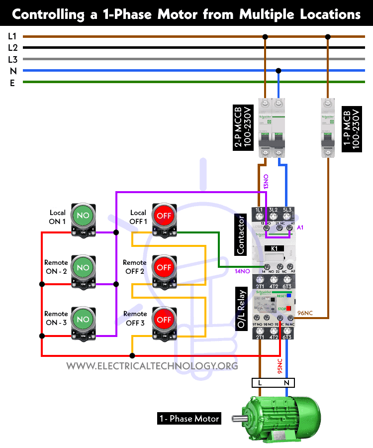
Controlling the ON-OFF Operation of a 1-Phase Motor from Multiple Places using Contactor and Pushbuttons
In large industrial and commercial premises, there are scenarios where we need to control a three-phase or single-phase motor from different locations. Similarly, we may need to control a water pump motor from different places in domestic and home applications. In the following wiring tutorial, we will discuss how to control the starting and stopping operations of a single-phase motor from different locations using a contactor and push-button switches, with the help of power and control circuit diagrams.
Related Posts:
- Auto & Manual Control of 1-Phase Water Pump Motor using Float Switch
- Auto & Manual Control of 3-Phase Water Pump Motor using Float Switch
Components Needed
- Single-Phase Motor
- Contactor
- Thermal overload Relay)
- 1-P & 2P-MCB
- 3 Nos. of NO/NC Pushbuttons
- Single Phase Supply
- Wires & Cables
Control Wiring Diagram
Wiring the Control Circuit
Power Circuit:
- Wire and connect the L1 and L3 terminals of the contactor to the 2-pole MCB via Phase and Line wires.
- Connect a 2-pole MCB to the single-phase 120V to 230V power supply, mainly from the 120V-240V panel, 230V consumer unit or distribution board.
- Wire and connect the L1 and L3 terminals of the contactor to the output of the 2-pole MCB via Phase and Line wires. Keep in mind that the O/L relay is already connected to the contactor.
- Connect the T1 and T3 terminals of the overload relay to the “L” and “N” terminals of the single-phase motor.
- Connect the earth/ground wire to the motor terminal for proper protection.
Related Posts:
- How to Start & Stop a 3-Phase Motor from Multiple Locations?
- How to Control a 3-Phase Motor from Multiple Places?
Control Circuit:
- Connect a wire to the first terminal of each start pushbutton (local and remote). Now, connect this wire to the 13-NO terminal of the contactor. Add a jumper wire between the 13-NO and A1 terminals of the contactor.
- Connect a wire to the second terminal of each start pushbutton (local and remote). Now, connect this wire to the 95-NC terminal of the thermal overload relay.
- Connect all three local and remote stop pushbuttons in series to the 95-NC terminal of the thermal O/L. Then, connect a wire from the last stop pushbutton to the 14-NO terminal of the contactor.
Working of the Circuit
- When the operator presses the local start pushbutton, the contacts close, leading to the energization of the contactor. Thus, the motor starts to run.
- When the operator presses the local stop pushbutton, the contacts open, returning to their initial state. This way, the contactor de-energizes, and the motor stops.
- The same process applies to all the additional remote pushbuttons installed in different locations to control the motor from various places.
- Due to the interlocking mechanism, only one operation (either stopping or starting) can be performed at a time. This prevents damage to the circuit and avoids overheating/burning the connected motor.
Related Posts:
- ON / OFF Control of a 3-Phase Motor Using a DOL Starter
- ON / OFF 3- Phase Motor Using 8-PIN Relay and DOL Starter
- ON / OFF 3- Phase Motor Using 14-PIN Relay and DOL Starter
- ON / OFF 3- Phase Motor Using 11-PIN Relay and DOL Starter
- Compressor Motor Control in Refrigeration Using Soft Starter
- Three Phase Slip Ring Motor Wound Rotor Starter
- Two-Speed, One-Direction, 3-Phase Motor Power & Control Diagrams
- Two-Speed, Two-Directions, 3-Phase Motor Power & Control Diagrams
- Dahlander Motor: Speed Control using Dahlander Connection
- Even More Power & Control Wiring Diagrams

 How Does a Standard Breaker Respond to Electrical Fault?
 Why Doesn’t a Standard Breaker Protract Against Ground Faults?
 How Do GFCI and Standard Breakers Respond to Ground Faults?
 What Happens if the Neutral is Lost in the Main or Subpanel?
 Why Must Neutral and Ground Wires Be Bonded in the Main Panel?
 Why are Neutral and Ground Wires Separated in a Subpanel?