How to Control a 3-Phase Motor using VFD and DOL starter for Auto and Manual Operations?
In industrial applications, controlling the speed and operation of motors is vital for optimizing energy consumption and process efficiency. VFDs offer an advanced solution for this purpose. However, situations may arise where a motor needs to run at full speed without VFD control, prompting the integration of a Direct-On-Line (DOL) starter with a VFD bypass mechanism. In this wiring tutorial, we will show how to automatically and manually control the speed and operation of a three-phase motor using VFD and DOL starter with the help of power and control wiring diagrams.
VFD & DOL Starter
A Direct-On-Line (DOL) starter (based on a contactor and additional thermal overload relay) is a basic motor control method where the motor is directly connected to the power supply, resulting in an immediate full-voltage start. DOL starters are cost-effective and suitable for applications where speed control is not essential.
On the other hand, a Variable Frequency Drive (VFD) is an advanced control solution that enables precise adjustment of motor speed and torque by varying the frequency and voltage supplied to the motor. VFDs offer energy efficiency, reduced mechanical stress, and enhanced process control, making them ideal for applications requiring variable speed operation and optimized energy consumption.
Components Required
- Three-Phase Motor
- 3-P MCCB
- 2-P MCB
- Variable Frequency Drive (VFD)
- DOL Starter (based on Contactor)
- 8-PIN Relay
- Single-Phase & Three Phase Supply
- Selector Switch for manual ON/OFF and DOL/VFD Operation
- External Start and Stop pushbuttons
- Wires & Cables
Wiring Auto/Manual Control of Motor using VFD & DOL Starter
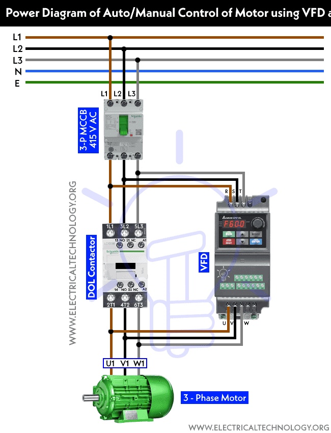
Power Diagram:
- Connect the DOL contactor’s terminals to the three-phase lines L1,L2 and L3 from 3-P MCCB.
- Connect the output of contactor (T1,T2 & T3) to the motor’s terminals (U1, V1 & W1)
- Now, connect the 3-phase lines from MCCB to the input terminals of VFD (R,S & T)
- Connect the output terminals of VFD (U,V & W) to the motor’s terminals (U1,V1 and W1) as shown in power diagram.
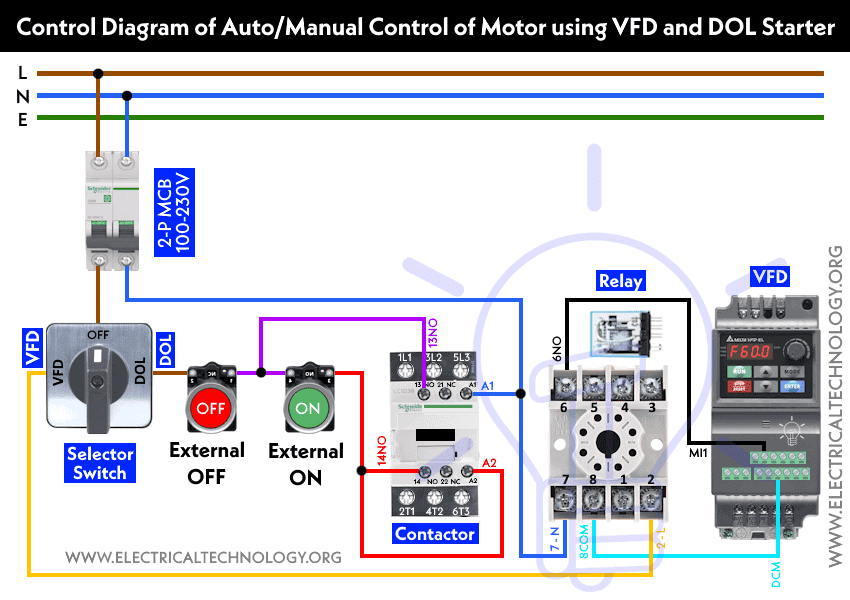
Control Diagram:
- Connect the phase line from 2-P MCB to the common (OFF) terminal of selector switch.
- Connect a wire from the 1st terminal (for VFD operation) from the selector switch to the 2-L terminal of 8-PIN relay.
- Connect a wire from the 2nd terminal (for DOL operation) from the selector switch to the two series connected external buttons (for External OFF and ON in case of manual operation i.e. bypassing VFD). Connect the second terminal of external ON pushbutton to the 14-NO and A2 terminals of contactor.
- Connect a wire from the starting terminal of ON pushbutton to the 13-NO terminal of contactor.
- Connect a wire from the VFD’s terminal (DCM – COM) to the 8-COM terminal of 8-PIN relay.
- Connect the MI1 terminal of VFD to the 6-NO terminal of 8-PIN PLA relay.
- Finally, connect the Neutral wire from 2-P MCB to the A1 terminal of contactor and 7-N terminal of relay as shown in the control circuit diagram.
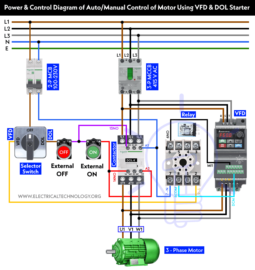
Power & Control Wiring Diagram
Working and Operation
Automatic Operation:
- Rotate the switch to the “VFD Mode”. The VFD will automatically adjust the speed and motor’s direction of rotation according to the specified program (via external program or keypad control button).
- The motor and VFD can be switched-OFF by rotating the selector switch to the OFF position.
Manual Operation:
- In case of emergency, or when you need to run the motor at full speed or want to bypass the VFD, simply rotate the selector switch to the “DOL position”.
- The motor will run at full load as it is now directly connected to the three-phase supply via DOL contactor.
- The external pushbuttons can be used to ON or OFF the motor.
- If you need to fully terminate the operation, simply rotate the selector switch to the OFF position.
- If you need switch the operation to operate the motor automatically via VFD, just rotate back the selector switch to the VFD mode. It will bypass the DOL starter and motor can be controlled automatically via VFD.
Related Posts:
- How to Reverse and Forward a Three-Phase Motor Using a VFD?
- Automatic & Manual Control of Motor Using VFD & DOL Starter
- VFD Bypass Star-Delta Starter – Power and Control Circuits
- VFD Bypass DOL Starter – Power, Wiring and Control Circuits
- ON / OFF 3- Phase Motor Using 14-PIN Relay and DOL Starter
- Automatic Star-Delta Starter using Timer – Power, Control & Wiring Diagrams
- Star – Delta Motor Control Circuit Using Omron PLC ZEN Programming Relay
- Reverse Forward Motor Control Circuit Using PLC & ZEN Programming Relay
- Reverse-Forward of 3-Phase Motor using DOL Starter
- Automatic Reverse – Forward Motor Control Circuit Using Omron CP2E PLC
- Automatic Reverse Forward Motor Control Using S7-1200 PLC
- Sequential Motor Control Circuit Using LOGO! V8 PLC
- Sequential Motor Control Circuit Using Mitsubishi FX5U PLC
- Sequential Motor Control Circuit Using Delta – DVP-14SS PLC


 Wire Nuts and Connectors Color Codes – Wire and Gauge Sizes
 Why is the Neutral Wire Size Smaller than the Phase Wire?
 Why is the Ground Wire Size Smaller than the Hot Wire?
 Why Do We Need a GFCI & How Does it Protect During Faults?
 How Does a Standard Breaker Respond to Electrical Fault?
 Why Doesn’t a Standard Breaker Protract Against Ground Faults?