Synchronous Motors – Working Principle, Types, Starting Methods and Applications
An electrical machine is a general term used for an electromagnetic device that is used for conversion between electrical and mechanical energy. It can be used as a generator to develop electrical energy or as a motor to develop mechanism energy. A synchronous motor is a type of motor that is used in industries for its constant speed.
Electric Motor
An electric motor is a machine that converts electrical energy into mechanical energy. It has a stator (stationary part) and rotor (moving part). When electrical energy is supplied, the rotor rotates generating rotational mechanical energy. It works completely opposite to that of a generator.
Electrical motors can be classified into AC and DC motors. While the AC motors are further classified into induction motors and synchronous motors.
What is a Synchronous Motor?
A synchronous motor is a type of AC motor whose rotor rotates at the same speed as the rotating magnetic field. The stator’s magnetic field revolves at a speed that depends on the supply frequency known as synchronous speed. Hence the name synchronous motor. The rotor of the synchronous motor is synchronized with the frequency of the supplied current.
When two synchronous generators are running in parallel operation and the prime mover of one generator is shut down. The generator will still run while taking power from the generator line. The alternator supplies the obtained power from the line to its losses. When a mechanical load is connected to it, the machine will run at constant speed. When a machine runs and operates the way mentioned above, it is known as a synchronous motor.
Unlike the induction motor, the synchronous motor does not rely on the induced rotor current instead the rotor has either permanent magnets or field windings that are energized using an external source. In an induction motor, the stator windings generate a rotating magnetic field (RMF) that also induces a current in the rotor. In a synchronous motor, the stator only generates RMF. The rotor’s magnetic field magnetically locks with the revolving RMF and rotates at the same speed known as synchronous speed.
Click image to enlarge
Good to Know: A synchronous motor is the same machine as Alternator or synchronous generator. For example, A synchronous motor can be operated as a synchronous generator (alternator) without changing the rating and design. i.e.
- When the machine converts the input electrical power into output mechanical power, it is known as a synchronous motor.
- When the same machine converts the input mechanical power into output electrical power, it is known to be a synchronous generator (alternator).
The synchronous motor is structurally similar to an alternator. It operates at a constant speed called synchronous speed, NS. It depends on the supply frequency and the number of poles in the rotor. Synchronous speed is given by
NS = 120f ÷ p
Where
- NS = Synchronous speed (RPM)
- f = Frequency of supply current
- p = No. of poles
The number of poles depends on the design of the motor and cannot be changed during operation. Therefore, the speed of the synchronous motor only varies with the supply frequency.
Related Post: Three-Phase Induction Motor – Construction, Working, Types & Applications
Construction of Synchronous Motors
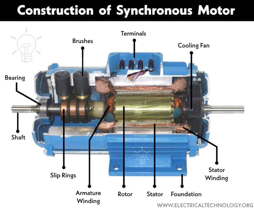
The construction of a synchronous motor is similar to an Alternator or Synchronous generator. it differs from an asynchronous or induction motor based on its rotor design.
A Synchronous motor has two main parts
- Stator
- Rotor
Stator
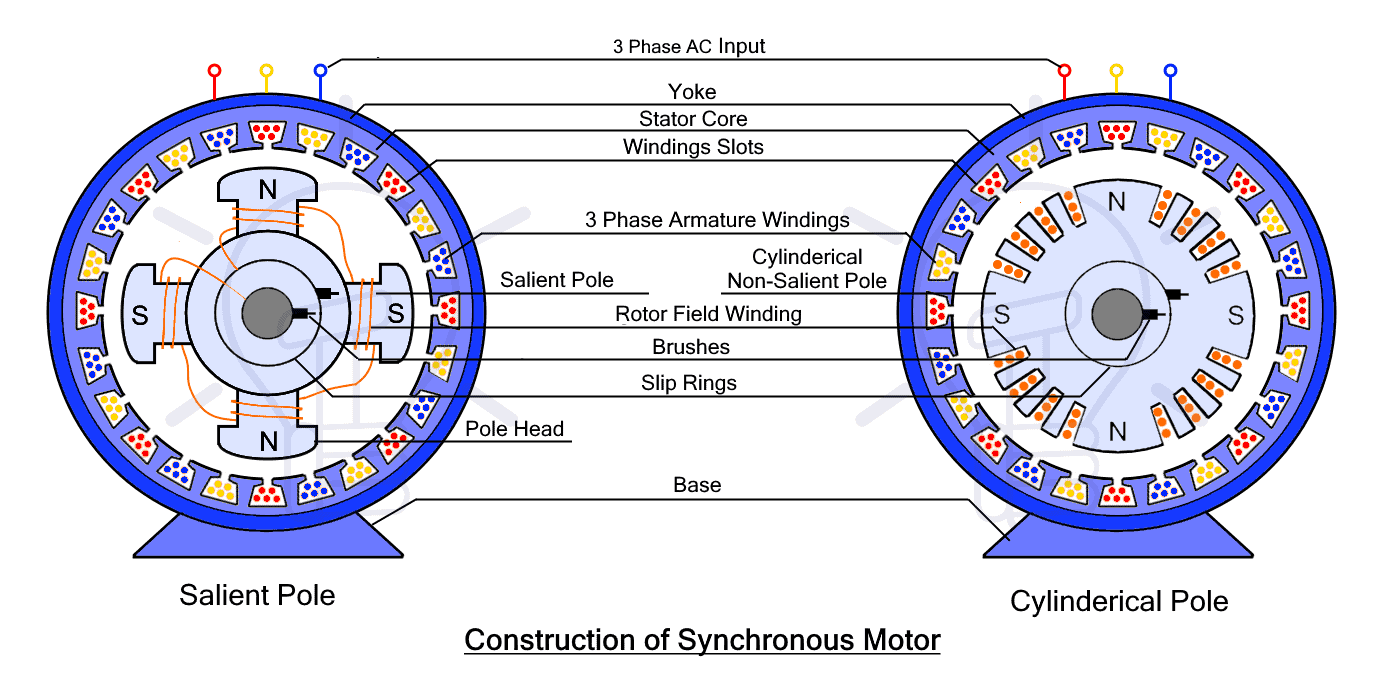
The stator is the stationary part of the motor. Just like an induction motor, the stator core is made of thin laminated sheets of steel or cast iron of good magnetic quality to reduce hysteresis and Eddy current loss. The core has axial slots for holding the three-phase alternating stator field winding called armature winding.
The stator’s armature winding is supplied with 3-phase power through its input terminal. It is responsible for generating the rotating magnetic field (RMF).
Rotor
The rotor is the rotating part of a synchronous motor. It has a cylindrical shape and holds the field winding, which is responsible for generating the magnetic field or poles. The rotor is energized using slip rings and a brush assembly, typically with a DC source. Usually, a small DC generator connected to its shaft is used for excitation.
The rotor of a synchronous motor can be designed in one of the following ways.
Salient Pole Rotor
The term ‘salient’ means ‘pointing outward’. The salient Pole rotor has protruding or projecting poles toward the armature winding. The rotor core is made of a laminated steel sheet for reduction in hysteresis and Eddy current. The field windings are wounded around each pole.
The salient Pole rotor has a large number of poles. It is not suitable for high-speed operation due to its high windage losses (at high speed). It is used in low and medium-speed synchronous motors. Physically, it has a large diameter and small axial length.
Slip rings and brush assembly is used to provide electrical connection between the stationary circuit and rotating part of a machine. It is used to energize the field winding using a DC source.
Non-Salient Pole or Cylindrical Rotor
Such type of rotor has a cylindrical shape rotor made of laminated steel. The core has slots for field windings that are secured with the help of wedges to prevent by pulled out. While the unslotted portion of the core becomes magnetic poles.
It has less number of poles, having smaller diameter and longer axial length. It is costlier than the salient pole rotor. However, the rotor design helps in uniform distribution of flux, mechanical strength, robustness, etc. Therefore such synchronous motors are used for high speed.
Permanent Magnet Rotor
Modern synchronous motors use a permanent magnet rotor where the rotor has permanent magnets mounted on its surface. There are no field windings. These magnets generate the necessary field without the requirement of an excitation source. The permanent magnet is made of neodymium-boron-iron since they are easily available and cost-effective. Such rotor does not have a slip ring or brush assembly.
The disadvantage of a permanent magnet rotor is that the motor is not self-starting due to the rotor’s inertia, it can’t follow the fast revolving RMF right at the startup. Therefore VFD (variable frequency drive) is necessary for its operation.
Working Principle of Synchronous Motor
Synchronous motor works on the principle of magnetic locking between the stator RMF (rotating magnetic field) and the rotor magnetic field. As we know, opposite poles attract each other, therefore the RMF poles attract the opposite rotor poles generating a rotating motion.
A synchronous motor is a doubly excited machine i.e. it requires AC and DC supply for both parts stator as well as rotor to achieve synchronism. A three-phase AC is supplied to the stator’s windings to generate RMF. The stator is designed to have the same number of poles as the rotor. These poles rotate at the speed that is in sync with the input frequency f is called synchronous speed. It is given by
NS = 120f / p
A DC supply is provided to the rotor’s windings to generate a fixed magnetic field. As the DC source supplies constant current, the rotor’s magnetic field does not vary. Magnetic poles are generated at the opposite ends of the rotor. The rotor’s poles interact with the RMF of the stator and rotate at the same speed as it attains the synchronous speed.
If the rotor rotates at the same speed as the stator RMF, there is no load torque. The rotor and stator poles align with each other. If a mechanical load is applied, the rotor starts oscillating about its new equilibrium position, this phenomenon is known as ‘hunting‘. The rotor lags a few degrees behind the stator RMF and starts developing torque. As the load is increased the angle between them is increased until the rotor field lags by 90° behind RMF. At this point, the motor provides the maximum available torque called breakdown torque. If the load exceeds this limit, the motor stalls.
Features of Synchronous Motor
- The synchronous motor is inherently not self-starting. The rotor needs to be brought up to the synchronous speed by any means to synchronize with the supply frequency.
- Its speed only varies with the frequency of the input supply. VFD is used to control the speed of the synchronous motor.
- Its speed is independent of the load. Therefore synchronous motor is not affected by any variation in the load.
- The Increase in load increase the torque. A synchronous motor will stall if the torque increase beyond the breakdown torque.
- Synchronous motor either run at synchronous speed or does not run at all.
- Synchronous motor can run in both leading as well as lagging power factors. Therefore they are used for power factor Improvement in industries.
Starting Methods of Synchronous Motors
A synchronous motor isn’t inherently Self-starting due to the rotor’s inertia. When power is applied, the stator RMF instantly starts revolving with synchronous speed. However, the rotor cannot keep up. To provide the necessary speed for the rotor to synchronize, the following methods are used.
Damper Winding
A damper winding is used in the salient pole rotor. It is a short-circuited winding just like in an induction motor. The RMF induces a current in this winding and generates its own magnetic field that interacts with the RMF and produces the required starting torque. When the rotor reaches near synchronous speed, the DC excitation is applied to the rotor field winding and the motor locks into synchronism.
In this method, the motor initially starts as an induction motor using the damper winding. This winding also helps in damping the oscillations due to sudden changes in load.
Pony Motor Method
A pony motor is a small induction motor or DC shunt motor that is connected with the shaft of a synchronous motor. It helps in providing the necessary starting torque. The DC excitation is not applied until the rotor attains speed near synchronous speed. The rotor magnetically locks with RMF and the power supply to the pony motor is cut off.
Variable Frequency Method
VFD or variable frequency drive is a device that provides power with adjustable frequency. As we know, synchronous speed depends on the supply frequency. Initially, the frequency is set to a minimum to reduce the synchronous speed. The speed is gradually increased to the desired value or normal speed.
Types of Synchronous Motors
The synchronous motor is mainly classified into two categories based on rotor magnetization.
DC Excited Motor
In such synchronous motor, a DC source is used to excite its rotor through a slip ring. The rotor includes field winding that is magnetized to generate a constant magnetic field that interacts with the stator RMF.
Non Excited Motor
The rotor of such a synchronous motor does not require external excitation to generate the magnetic field. Instead, it is made of material that generates its own field such as in a permanent magnet or with the help of the stator field. Cobalt steel is usually used due to its high retentivity (material that stores magnetic properties).
Non Excited Motor can be further classified into the types
- Permanent Magnet Synchronous Motor
- Hysteresis Synchronous Motor
- Reluctance Synchronous Motor
Permanent Magnet Synchronous Motor
As the name suggests, the rotor is made of a permanent magnet that generates a constant magnetic field. There are no windings, slip rings and brushes. The rotor field locks with the stator RMF and rotates at synchronous speed. Since they are not self-starting and there are no windings in the rotor, it requires VFD to provide gradual increases in starting speed.
Hysteresis Synchronous Motor
The rotor of such synchronous motor is made of a material having high hysteresis loss such as chrome, and cobalt steel. It is a self-starting single-phase motor that runs at synchronous speed. It has two stator windings i.e. ‘main winding’ and ‘auxiliary winding’ to generate the stator RMF. The cylindrical rotor starts rotation due to induced Eddy current, thus it starts like an induction motor. Once it achieves near synchronous speed, the stator RMF locks the rotor into synchronism.
Reluctance Synchronous Motor
Such synchronous motor works on the principle of reluctance. Under the influence of a magnetic field, a ferromagnetic material will move to complete the magnetic circuit where there is minimum reluctance. Magnetic field lines follow a low reluctance path just like current follows a low resistance path.
Therefore, a squirrel cage type rotor is used with some teeth removed to form a salient pole as well as less reluctance path. The stator is similar to the hysteresis motor having main and auxiliary windings to generate RMF. At startup, the rotor tries to align with RMF and starts revolving in its direction. But due to rotor inertia, RMF passes the alignment position and tries again during the next revolution. Thus the speed gradually increases and eventually reaches the synchronous speed and magnetically locks with the RMF.
Advantages & Disadvantages of Synchronous Motor
Advantages
Here are some advantages of synchronous motor
- It has a constant operating speed called synchronous speed that only depends on supply frequency and does not vary with any change in load.
- It can operate in lagging, unity and leading power factor by increasing the field excitation. Thus making it useful for power factor improvement.
- It has a relatively higher efficiency above 90% as compared to the induction motor.
- They are more cost-effective at a lower speed than an induction motor.
Disadvantages
Here are some disadvantages of synchronous motor
- Synchronous Motors are inherently not self-starting and require other means to provide near synchronous starting speed.
- It stalls if the load exceeds beyond breakdown limit.
- It requires an external DC source for its rotor field excitation
- Its speed cannot be varied unless the VFD variable frequency drive is used to very its supply frequency.
- Hunting occurs in synchronous motor with sudden application of load.
- It requires frequent maintenance due to slip rings and brushes.
- Synchronous motors are generally more complicated and costlier than induction motors.
Related Post: Motor Efficiency and How to improve it?
Applications of Synchronous Motors
Here are some common applications of synchronous motors.
- Constant Speed Application: They are usually used in constant speed applications where the speed does not vary with increasing load. However, VFD can be used to adjust its speed according to requirements.
- Power Factor Correction: By changing the excitation of the synchronous motor, the power factor of the electrical circuit can be varied. Such synchronous motor that is specifically used to improve the power factor is called a synchronous condenser.
- Frequency Changer: A synchronous motor is used to run an alternator or synchronous generator to supply having a different frequency. Such a synchronous motor is known as a frequency Changer.
- Voltage Regulation: Synchronous motor can act as a variable capacitor or inductor by varying its excitation. It is used for voltage regulation by controlling the reactive power in a long transmission line.
- Very low-speed Applications: Using very low frequency, synchronous motor can be used for very low-speed applications with high efficiency.
- Positioning: Due to their constant speed, they are used for precise positioning in robotics just like servo motors.
- General Applications: Synchronous motors are widely used where constant speed is needed. In addition, these kind of motors are used in grinders, pulp beaters, rock crushers, ball mills, steel mills, metal rolling mills, cement mills, rubber and textile mills, centrifugal pumps, air compressors, fans, blowers, line shafts, turn tables, timers, clocks, juicers, tap recorders and players, mixtures, signaling devices, photographer, indicating, regulating ad controlling devices.
Related Posts:
- Motor Starter – Types of Motor Starters and Motor Starting Methods
- Direct Online Starter – DOL Starter Wiring Diagram for Motors
- Cable Size Calculation for LT and HT Motors
- Speed Control of DC Motor – Voltage, Rheostatic & Flux Control Methods
- What is Motor Generator Set and How Does it Work?
- Electrical Transformer – Construction, Working, Types and Applications
- Alternator or Synchronous Generator: Construction, Working, Types & Applications
- Electric Motors Symbols
- Speed Control of DC Motor – Voltage, Rheostatic & Flux Control Methods
- AC Drive – Working and Types of Electrical Drives & VFD
- DC Drive – Working and Types of DC Drives
- Three Phase Motor Power and Control Wiring Diagrams
- Electric Motors Symbols
- Applications of Electric Motors


 Rotor Balancing in the Motors – Types, Methods and Importance
 Difference Between Static Balancing and Dynamic Balancing
 What are the Cuts on the Rotor of Motor’s Armature?
 Difference between Voltage Source Inverter & Current Source Inverter
 Difference Between Voltage Stabilizer and Voltage Regulator (AVR)
 Difference Between Servo Motor and Stepper Motor