What is the Difference Between 1-Phase Transformer & 3-Phase Transformer?
We all know that a transformer in an electrical machine, which is used to step-up or step-down the level of alternating voltage and current for power transmission from the generating stations to the homes as residential and industries as commercial applications.
Despite the different applications of transformers, there are two main types of transformers based on supply systems e.g. single phase transformer and three phase transformer.
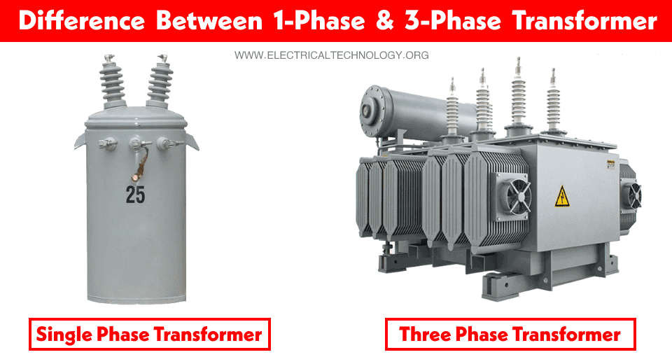
The main difference between a single phase transformer and a three phase transformer is that the single phase transformer provides a single phase supply to the circuits via two conductors viz Phase (Line) and Neutral (1P + 1N) whereas the three phase transformer provides a three phase supply via three phases (Lines) and a neutral conductor (based on the system requirement) if needed (3P+1N).
Related Posts:
- Difference Between Power Transformers and Distribution Transformers?
- Difference Between Ideal and Real or Practical Transformer
Single Phase Transformer
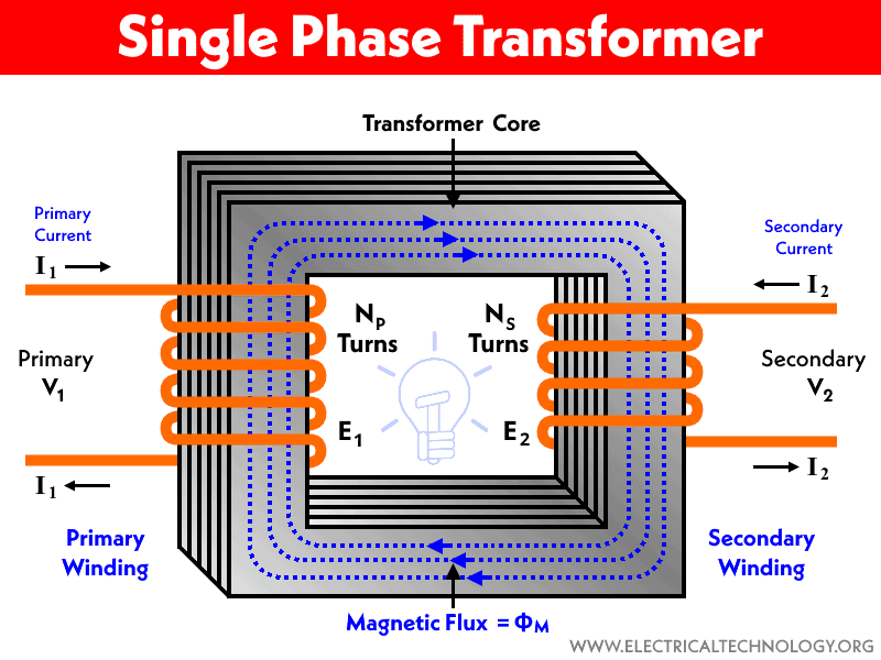
A single phase transformer is a single pair coil wrapped around the core. The pair coil as primary and secondary windings are electrically insulated from each other. It has 4-Terminals (2 for primary and 2 for secondary) as Phase and Neutral. There is no complex configuration for windings (such as Star or Delta) and both the Phase and Neutral wire is needed to complete the circuit.
In the US, the primary side of a single phase transformer is connected to the 7200V and the secondary provides 120V & 240V single phase voltage. In UK and EU and IEC following countries, the primary is connected to the 11kV and the secondary provides 230V single phase supply to the end users.
Single phase transformers are mounted on the utility poles near homes and mainly used in North America. They are less costly having low capacity, hence used for home and lighter load (residential and domestic applications).
Related Posts:
- Advantages of a Three Phase Transformer over a Single Phase Transformer
- Advantages of Three Phase System Over Single Phase System
Three Phase Transformer
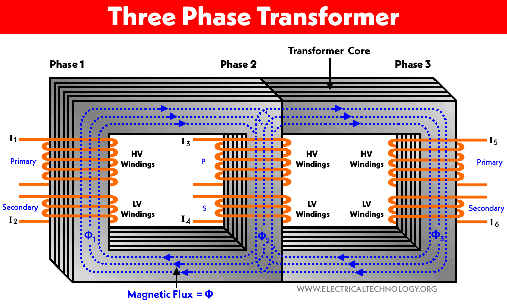
It is basically three single phase transformers interconnected in a single unit. Alternatively, three pairs of high inductive coils set is wrapped around a single core in different configurations such as Delta – Delta (Δ-Δ), Delta – Star (Δ-Y), Star – Star (Y-Y), Star Delta (Y-Δ) and many other arrangements based on the system requirements.
In the US, the primary side of a three phase transformer is connected to the 7200V and the secondary provides both single phase and three phase voltage levels such as 120V & 240V, 208V, 277V, 480V etc. In UK and EU and IEC following countries, the primary is connected to the 11kV and the secondary provides 230V single phase and 400V three phase supply to the end users (both domestic and industrial costumers).
3-Phase transformers are generally used in power generating stations (to step up the level of voltage and transmit high power) and provide three phase supply voltage to the customers having a demand of high power such as industrial and commercial applications.
Related Posts:
- Difference Between Single Phase and Three Phase Power Supply
- Difference Between Single Phase & Three Phase Induction Motor
Key Differences between 1-Φ and 3-Φ Transformers
Following are the main differences between a 1-phase and a 3-phase transformer.
| Single Phase Transformer | Three Phase Transformer |
| It has one set of primary and secondary windings which are mostly used in North America. | It has three sets of primary and secondary windings which are connected in Star or Delta Connections. |
| It is a single unit of two windings (Primary & Secondary). | It is a bank of three connected single phase transformers in a single unit. |
| The primary (low windings as first layer) and secondary (high voltage as second layer) windings are connected in simple and basic design on the main core which are electrically insulated from each other via an insulated medium such as oil which is used as cooling method of transformer. | The primary and secondary windings may be configured as follows.
|
| The primary is connected to 7200V US & 11kV in UK & EU and Secondary provides single phase 120V & 240V in US and 230V in UK & EU. | The primary is connected to 7200V US & 11kV in UK & EU and Secondary provides both single phase and three phase e.g. 120V & 240V, 208V, 277V, 480V etc. in US and 400V (3P) & 230V (1P) in UK & EU. |
| It provides single phase supply via One Phase and One Neutral Wire (1L + 1N). | It provides Three phase supply via Three Phases and a Neutral Wire (3L+1N) or only 3 Phases conductors. |
| It is not possible to get a three phase supply from a single phase transformer. | Both single phase and three phase supplies can be obtained from a three phase transformer. |
| Conversion of three phase supply from a single phase transformer is a little bit complex and expensive. | No need to use extra devices to convert a three phase supply into a single phase system as it has it as a built-in feature. |
| Power transmission capacity is less because of one phase conductor. | Power transmission capacity is high because of three phase conductors. |
| It costs less. | Cost is little bit higher |
| Small in size | Bigger size |
| Power transmission is less because of one phase conductor. | Electric Power transmission is high because of three phase conductors. |
| Designed in small ratings and used for small loads. | Designed in high rating and used for larger loads |
| In case of fault on the single phase transformer, the whole system connected to it shuts down. | In case of fault on one line (secondary), the load connected to the other two lines are working perfectly. |
| Single phase transformers are mostly used for power distribution purposes for end users e.g. domestic and residential applications. | Three phase transformers are used for power transmission purposes in power generating stations e.g. industrial and commercial applications. |
Related Posts:
- Applications of Transformers
- What is an Ideal Transformer?
- Parallel Operation of Single-Phase & Three-Phase Transformers
- Transformer’s Losses- Types of Energy Losses in a Transformer
- Open Circuit and Short Circuit Test of a Transformer
- Sumpner’s Test or Back-To-Back Test on Transformer
- Scott-T Connection of Transformer
- Polarity Test of a Transformer – Circuit Diagram and Working
- EMF Equation of a Transformer
- Equivalent Circuit of Electrical Transformer
- What is the Transformer’s Voltage Regulation?
- Transformer Efficiency, All day Efficiency & Condition for Maximum Efficiency
- The Dot Convention and Dot Notation in a Transformer Phasing
- Transformer Performance & Electrical Parameters
- Power Transformer Protection and Faults
- Transformers Fire Protection System – Causes, Types & Requirements
- Can We Replace a 110/220 Turns Transformer with 10/20 Turns?
- Electrical Transformer Symbols – Single Line Transformer Symbols
- Can We Operate a 60Hz Transformer on 50Hz Supply Source and Vice Versa?
- Which Transformer is More Efficient When Operates on 50Hz or 60Hz?
- Transformers (MCQs With Explanatory Answers)


 What is the Correct Wire Size for 100A Breaker and Load?
 Poland Builds Solar-Powered Bike Lane That Glows Blue in the Dark
 Wave, Wind, and Solar Hybrid Energy Raft Could Power 1,000 Homes a Day
 Dubai Airports to Install World’s Largest 60,000 MWh Solar Roof
 US Firm Unveils Small Nuclear Reactor to Power 300K Homes
 US Firms Plan Nuclear Battery Nickel-63 with 50-Year Lifespan to Counter China