
Why to use Shunt Reactors? Different between Power Transformer & Shunt Reactor
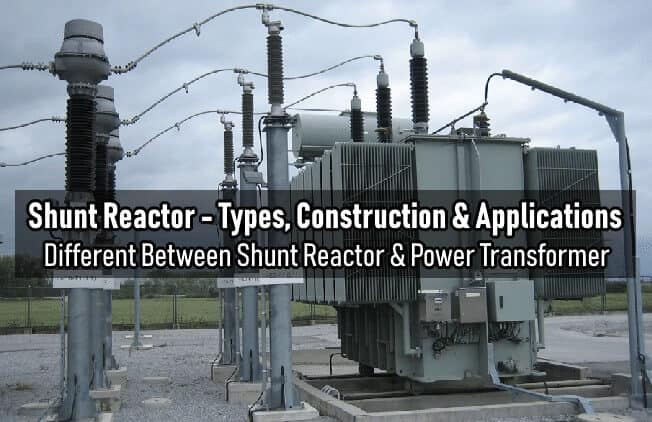
What is Shunt Reactor?
Shunt reactor is same as power transformer but it has only one winding per phase as compared to power transformer. Shunt reactors are used to increase the power and energy system efficiency as it absorb & compensate the reactive power in cables and long high voltage transmission lines. It can be directly connected to the power line or tertiary winding of three winding transformer.
- Related Post: Power Transformer Protection & Faults
Different Between Shunt Reactor & Power Transformer
Both Shunt reactor and power transformer are same in construction but there are some main difference as well such as:
- Shunt reactor has only single winding while Power transformer has three windings.
- Shunt reactor provide lagging VArs (Or it may consume and absorb reactive power) to increase the system efficiency while power transformer is meant to be operated to transform voltage (i.e. step up or step down)
- In shunt reactor, primary AT (Ampere Turns) are equal to secondary AT due to the absence of other windings while in case of power transformer, Primary AT is the sum of exciting AT and Secondary AT.
- Shunt reactor may be designed without air or iron core to prevent the hysteresis loss as there are large amount of magnetizing current as compared to power transformer.
- Shunt Reactors are rated in MVAr while power transformer rated in kVA.
- Shunt reactor are used in high voltage systems and cables network to improve the system efficiency while power transformer are used to transfer the level of voltage.
Related Post: Transformers Insulation Materials in Oil-Immersed & Dry Type T/F
Why to use Shunt Reactor ? Applications of Shunt Reactors
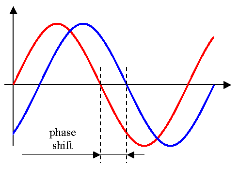
Apart from resistance real electrical circuits have a inductive and/or capacitive component, which causes a phase shift between voltage and current, as shown in Figure 1, and reactive power (unit: VAr) will flow in the circuit.
If inductance (XL = 2πfL = ωL) prevails current will be lagging (Figure 2) and reactive power is called inductive power.
Where:
XL (Ω – ohm): Inductive reactance. f (Hz – hertz) : frequency. L (H – henry): Inductance. ω = 2πf: Rotational speed (rad/s or rpm – radians per second or revolutions per minute)
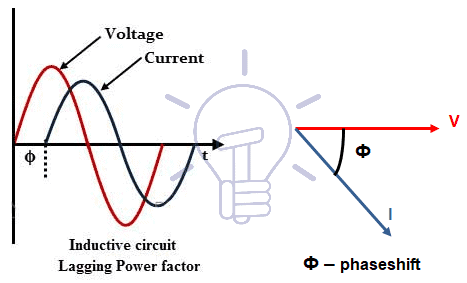
This is the case of long overhead lines. The consequence of lagging currents is well known (low power factor), as well as the way to increase power factor (installation capacitor banks).
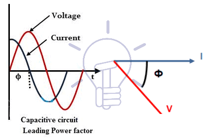
If capacitance prevails (XC = 1/2πfC = 1/ωC ), which is the case of networks with long underground cables.Current will be leading (Figure 3) and reactive power is called capacitive power.
Where:
XC(Ω– ohm): Capacitive reactance. C (F – farad): Capacitance.
This situation is also harmful for power transformers and mainly for generators.
Power transformers may be subjected to ferroresonance, an over-voltage phenomenon that can damage the transformers and/or the surge arresters .In weak networks, functioning as an island and not integrated in a large and complex electrical network, generators are requested to supply the excessive capacitive power, situation that will cause overheating and malfunctioning of generators, which will decrease the useful life of the equipment.
That excessive reactive power must be compensated, using shunt reactors, equipments that shall be in accordance with IEC Standard 60076-7, of which an example is shown in Figure 4.
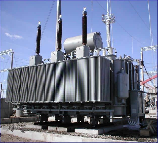
Construction of Shunt Reactor
As mentioned above, Shunt reactors are similar to power transformers, but they have only one winding per phase.
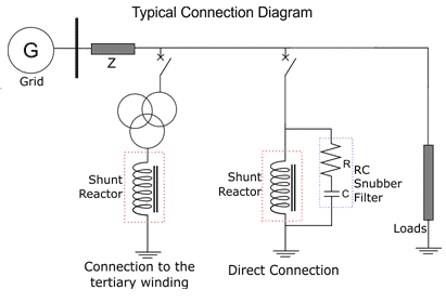
Those three windings are star connected with the neutral point accessible (YN). The neutral point is connected to the earthing system of the installation through the tertiary winding of a power transformer or directly. Figure 5 shows a typical connection diagram of a shunt reactor.
Shunt reactors may be oil-immersed type with conservator or dry type.
The built-on protections are the same used in power transformers (Buchholz relay and oil pressure and temperature sensors for oil-immersed type; windings temperature probes for dry type). Accessories are also similar to those used in power transformers, mainly in oil-immersed type, in which it must be emphasized the oil pressure relief valve and the air breather.
Types of Shunt Reactors
Common shunt reactors have a fixed rating ( MVAr ; kVAr ) and they may be permanently connected to the network, or switched in and out, depending on the load and of the capacitance of the underground cables in service. This functioning and the switching in and out are similar to what is done with capacitor banks.
The more recent technology calls, depending of the characteristics of the network and the variability of the load, for the use of variable shunt reactors (VSR), which rating can be changed by steps. Common shunt reactors are mainly used in medium voltage networks (up to 36 kV).
VSR are mainly used in extra high and high voltage networks (rated voltage of the network ≥ 60 kV).
Maximum rated voltage of shunt reactors is nowadays 800 kV and rated power goes up to 300 MVAr.
Same like power transformers, shunt reactors may be designed like Oil-immersed and Dry type transformer as well.
-
 Why are Capacitors Connected in Series in Power Lines?
-
 Why is a Capacitor Bank Connected in Parallel and Not in Series for P.F?
-
 Why Does Japan Use Both 50Hz and 60Hz in Its Power System?
-
 Why is the Neutral Wire Size Smaller than the Phase Wire?
-
 Why is the Ground Wire Size Smaller than the Hot Wire?
-
 Why Must Neutral and Ground Wires Be Bonded in the Main Panel?