Public Street & Road Lighting – General Principles, ISO & IEC Standards
Lighting Basic Parameters
Basic parameters used in lighting are:
- Luminous flux – notation: Φ ; unit: lumen ( lm ).
- Luminous intensity – notation: I; unit: candela ( cd ).
- Illuminance – notation: E; unit: lux ( lx or lux ).
- Luminance – notation: L; unit: cd / m2 [ 1 cd/m2 ≈ 10 lux ]
- Uniformity ratio – notation: U = E(average) / E(minimum)
Recommended Lighting Levels
Public lighting is done using specific lighting fixtures mounted in poles; this subject will be analyzed in next post of this publication.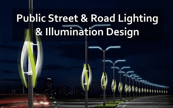
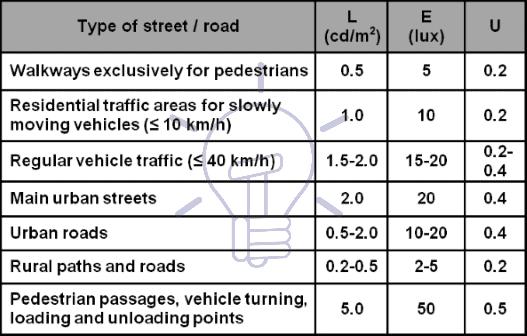
Taking into account the type and the use of streets and roads, the recommended lighting levels and uniformity ratio, according to European Standard EN 12464-2: Lighting of work places – Part 2: Outdoor work places are indicated in table 1.
- Related Read: Star and Delta Connected Lighting Loads
Table 1 – Values of L, E and U for street and road lighting
- Also Read: Light Emitting Elements And Their Types
Calculation of lighting levels is done using specific software, like DIALUX, and must take into account the type and the width of the street/road, the mounting height of the lighting fixture, the length and the angle of inclination of the pole bracket, the type of lighting fixture and the type and rated power of the lamp (that defines the lamp luminous flux).
It also must be defined the type of distribution of the poles along the street/road: single sided (Figure 1); double sided (Figure 2); staggered sided or zigzag pattern (Figure 3); central verge position (Figure 4).
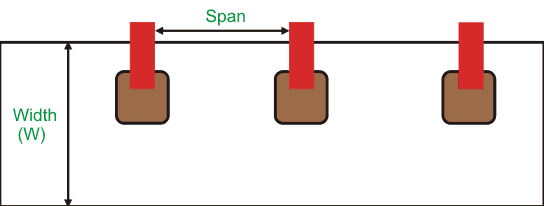
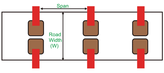


To a first approach to evaluate the distance or the span between poles (d) and their recommended distribution the following rules may be used, being h the mounting height of the lighting fixture and l the width of the street/road:
1) d ≈ 3-3.5 x h
2) Single sided pole distribution: l ≈ h
3) Double sided or central verge pole distribution: l ≈ 2 x h
4) Staggered sided pole distribution: l ≈ 1-1.5 x h
Lighting Fixtures, Lamps and Poles
Fixtures for public lighting must be in accordance with IEC (International Electrotechnical Commission) Standards 60598 – Luminaires and 62722 – Luminaire performance, and are usually equipped with 70 W, 100 W, 150 W or 250 W high-pressure sodium lamps with improved color rendition, or according to the most recent technology, with LED lamps with lower power for the same luminous flux.
The IP code of lighting fixtures shall be no lower than IP 65, according to IEC Standard 60529 – Degrees of protection provided by enclosures (IP Code) and diffusers shall be anti-vandal protected, preferentially in poly carbonate.
Related post: What is the objection to have lamps in a house-lighting circuit connected in series?
The luminaires should be a standard type that is maintainable by and approved by the municipality, the office of traffic or, where applicable, by the power utility company.
Poles shall be preferentially metallic, hot dip galvanized; surface treatment must be in accordance with the following standards: EN ISO 14713, ISO (International Organization for Standardization) 2063 and EN ISO 12944: Part 5.
Poles with a nominal height (Distance between the center line of the point of entry of the lighting fixtures and ground level.) ≥ 6-8 m it is usual that they have an octagonal shape and they may have one or two brackets with lengths from 0.5 to 2 m and inclination varying between 5º and 15º. In Figure 5 is shown a pole with two brackets.

- Also Read: Automatic Street Light Control System.(Sensor using LDR & Transistor BC 547.) Very Simple.
Poles are plate mounted, either on an in-ground section or concrete foundation and they must be equipped in base compartment with door, which provide access and protect electrical equipment of pole.
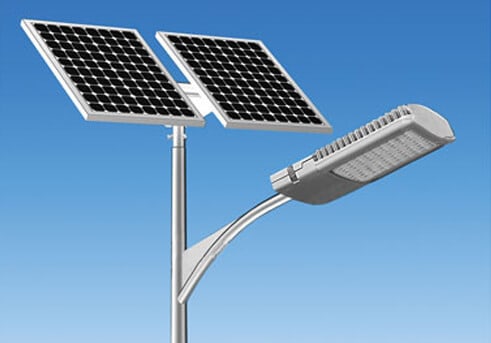
Nowadays is becoming increasingly the use of poles with photo voltaic panels, like is shown in Figure 6.
- Related post: Energy Efficient Lighting and Techniques to Implement It
In rural areas with overhead distribution networks (either with bare conductors or insulated cables) is common practice to install public lighting fixtures in the same poles of the distribution networks, using mounting brackets, solution that is shown in Figure 7.

- Related article: Lighting Design Calculation in a Building – Step by Step
 How Does a Standard Breaker Respond to Electrical Fault?
 Why Doesn’t a Standard Breaker Protract Against Ground Faults?
 How Do GFCI and Standard Breakers Respond to Ground Faults?
 What Happens if the Neutral is Lost in the Main or Subpanel?
 Why Must Neutral and Ground Wires Be Bonded in the Main Panel?
 Why are Neutral and Ground Wires Separated in a Subpanel?