
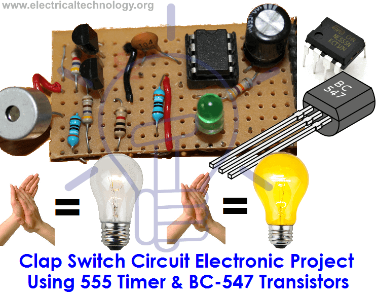
Clap Switch Circuit Electronic Project Using 555 Timer & BC-547 Transistors
Introduction to Clap Switch Circuit
Clap Switch is a basic electronics mini-project, made with the help of the basic components. Clap Switch has the ability to turn ON/OFF any electrical component or circuit by the clap sound. We will use two basic clap switch circuit diagrams i.e. (With IC 555 Timers and without 555 Timer).
It is known as Clap Switch because the condenser mic which will be used in this project will have an ability to take the sound having the same pitch as the clap sound as the input. Although it doesn’t mean that the sound will have to be exact the clap sound, it can be any sound having the same high pitch as clapping sound. We can also say that it converts the sound energy into the electrical energy because we are giving an input to the circuit as a sound whereas the circuit gives us the output as an LED light when glows (electrical energy). In more simple words, the circuit is able to convert the sound energy to activate the circuit and led provide electrical energy as an output in the form of heat and light.
Related Electronic Projects:
- Automatic Plant Watering & Irrigation System – Circuit, Code & Project Report
- Smart Irrigation System – Circuit Diagram and Code
Also Check:
- Traffic Light Control Simple Electronics Project using IC 4017 & 555 Timer
- IC 555 Timer Online Calculator with Formulas and Equations
Required Components
As already mentioned, this project is basic electronics mini-project, so this project is made of the basic electronic components.
Following is the list of the components required to make the Clap Switch.
- 1k, 4.7k, 47k, 330 and 470 ohms resistors
- 10µF and 2 100nF capacitors
- Electric condenser Mic
- Two BC547 transistors
- LED
- 555 Timer
- 9V battery
Working Principle of Clap Switch Circuit
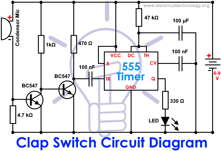
This circuit (As shown below) is made with the help of Sound activated sensor, which senses the sound of Clap as input and processes it to the circuit in order to give the Output. When sound is given as the input to the Electric Condenser Mic, it is changed into the Electrical Energy as the LED turns on. LED turns ON, as we give sound input and it turns OFF automatically after a few seconds. Turn-On LED timer can be changed by varying the value of 100mF capacitor as it is connected with 555 timer whose main purpose is to generate the pulse.
Although the name of the circuit is the Clap Switch, you are not restricted to give input as the Clap only. It can be any sound, having the same pitch as of Clap so this can also be called as “Sound Operated Switch”. This circuit is mainly based on transistors because the negative terminal of Mic is directly connected with the transistor. In this circuit, we haven’t used any Electronic Switch to turn on/off the circuit, so when you are connecting the battery with the circuit, it means your circuit is now turned ON and it will take the inputs in the form of Sound Energy. You can modify this circuit by using Relay as Electronic Switch to turn the circuit ON or OFF.
As soon as we give the sound input to the circuit, it amplifies the sound signals and proceeds them to the 555 timer which generates the pulse to the LED, making it turn ON. You are to make sure, that the negative side of the Condenser mic is connected with the amplifier or the circuit will heat-up and may not work with different models of transistors etc. You cannot increase the sensitivity of the Condenser mic for long usage, it has a short range by default. It is also applicable to the LAMP and fans and other electrical appliances, so this circuit has many opportunities for modification.
- Related Project: Voice Recognition Based Home Automation System
Clap Switch Schematic Circuit without 555 Timer
To make the same circuit as mentioned above without IC 555 Timer, We will have to use the following basic electronic components and devices.
| S. No | Component Name | Code | Value | S. No | Component Name | Code | Value |
| 1 | Resistor | R1, R9, R12 | 2.2kΩ | 10 | Capacitor | C2 | 1µF /50V |
| 2 | = | R2 = | 470kΩ | 11 | = | C4 | 47µF /16V |
| 3 | = | R3 = | 47Ω | 12 | Diode | D1, D2 | IN4148 |
| 4 | = | R4, R6 = | 4.7kΩ | 13 | LED | D3 | Red |
| 5 | = | R5, R8, R10, R11, R13 | 10kΩ | 14 | Transistors | Q1, Q2, Q3, Q4 | 9013 |
| 6 | = | R7 | 470Ω | 15 | Microphone | MK1 | 9767 |
| 7 | = | R14 | 1K | 16 | Cable Terminal | J1 | 2.45 2P (Horizontal) |
| 8 | Capacitor | C1, C5, C6 (Ceramic) | 104 (0.1μF) | 17 | Power Wire | 1 | 2.45 2P (Single) |
| 9 | = | C3 (Ceramic) | 103 (0.01μF) | 18 | PCB | 1 | FR-4 28*49 |
Related Post: Automatic Street Light Control System.(Sensor using LDR & Transistor BC 547.)
How Clap Switch Circuit Works without 555 Timer?
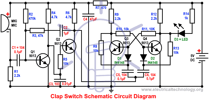
This circuit operates based on bi-stable trigger and audio frequency signal.
Audio signal accepted by MK1 goes to the base of transistor Q1 through capacitor C1. When amplified, it goes to the base of transistor Q2 through collector of transistor Q1. The bi-stable circuit trigger when they get a negative square wave from collector of transistor Q2.
Resistor R1 and capacitor C1 restrict the circuit frequency to high sensitivity range of 3kHz. When the power supply is ON, transistor Q3 saturated and Q4 is cutoff, so the diode D3 is OFF. When the MK1 microphone gets a control signal (clap or any other similar sound), The amplified negative square wave and negative pulse enters to the base of transistor Q3 through diode D1 after differentiation process. So the power turn ON and D3 LED diode glows.
The power turn OFF again when a control signal enters to MK1 microphone which leads the LED diode D3 switch off. To use other external control devices and equipment, J1 (Cable terminal can be used for this purpose). J1 and relay can be connected to control other appliances by clap or sound control system. Keep in mind that a reverse diode should be connected at the end of the relay to perform this operation.
Note: The operated voltage for clap switch circuit without timer is 5V DC while 6mA current is needed to glow the LED light (When current is less than 3mA, LED won’t glow).
Related Electron Projects:
- Automatic Bathroom Light Switch Circuit Diagram and Operation
- Automatic Doorbell with Object Detection By Arduino
Click schematic diagram to enlarge
Advantages & Disadvantages of Clap Switch Circuit
- It can be used to turn ON and OFF the LED or LAMP simply, by clapping your hands.
- We can also remove LEDs and place a FAN or any other electric component on the output in order to get the desired result.
- The Condenser Mic used in this circuit has the short range as a default, which cannot be varied.
Applications of Clap Switch Circuit
Clap Switch is not restricted to turn the LEDs ON and OFF, but it can be used in any electric appliances such as Tube Light, Fan, Radio or any other basic circuit which you want to turn ON by a Sound.
You may also check these simple and easy DIY EE Projects: Electrical and Electronics Projects
Related Basic Electronic Projects:
- Electronic Circuit Breaker – Schematic and Working
- Fully Automatic Water Level Controller using SRF04
- USB Propeller LED Fan Clock – Circuit Diagram & Project Code
- 24V Flasher Circuit
- Early Flood Detection System Using Arduino – Source Code
- 12V to 5V Converter Circuit – Boost and Buck Converters
- Dual Power Supply Circuit Diagram – 230VAC to ±12VDC
- Basic Voltage Doubler Circuit Diagram using 555 Timer IC
- How to Make a Voltage Tripler Circuit?
- Simple Cell Phone Charger Circuit Diagram – 5V from 230V AC
- Automatic Railway Gate Control System – Circuit & Source Code
- Electronic Relay Switch Circuit – NPN, PNP, N & P Channel Relay Switches
- LED Roulette Circuit Diagram using 555 Timer & 4017 Counter
- Distance Measurement Using Arduino and Ultrasonic Sensor
- Variable Power Supply Using Arduino UNO – Circuit and Code
- Simple Overvoltage Protection Circuit using Zener Diode
- Top Electrical Projects ideas for Engineering Students
-
 How to Size a Branch Circuit Conductors with Protection?
-
 How to Size Feeder Conductors with Overcurrent Protection
-
 How to Size Service-Entrance Conductors and Feeder Cables?
-
 How to Size Equipment Grounding Conductor (EGC)?
-
 How to Size Grounding Electrode Conductor (GEC)?
-
 Grounding and Methods of Earthing in PV Solar System