Two-Speed, Two-Directions, 3-Phase Motor Power & Control Diagrams
How to Control a 3-Phase Motor for 2-Speed and 2-Directions using Dahlander Connection?
The control of two-speed, two-direction three-phase motors plays a critical role in various industrial applications that require versatile and efficient machinery operation. One of the methods employed to achieve this control is through the Dahlander connection, a specialized winding arrangement that allows for two different speeds and directions of rotation. In this article, we will show the Dahlander connection and how it enables the control of a two-speed, two-direction three-phase motor with the help of power and control wiring diagrams.
Related Posts:
- Two-Speed, One-Directions, 3-phase Motor – Power & Control Diagrams
- Three-Speed, One-Directions, 3-Phase Motor – Power & Control Diagrams
Two-Speed, Two-Direction Operation
Two-speed, two-direction three-phase motors have two distinct speed settings (usually high and low) and can rotate in both clockwise and counterclockwise directions. Achieving this level of control requires the use of specialized control techniques.
- Direct-On-Line (DOL) Starter
- Star-Delta Starter
- Electronic Motor Drives (VFD)
- Microcontroller-Based Control
In the following article, we will discuss the basic way to control a three-phase motor for 2-speed and 2-direction using contactors and changeover or pushbuttons.
The Dahlander Connection
The Dahlander connection, also known as the Dahlander winding or the star-delta winding, is a configuration of motor windings that enables two different speed settings without the need for external switches or additional control circuits. It achieves this by connecting the motor’s windings in two different configurations, commonly:
- STAR/STAR and STAR
- STAR and STAR/DELTA
- DELTA/STAR and STAR
In this configuration, each phase has a set of windings per phase (i.e. two coils per phase) where total of 6 nos. of terminals can be wired for different speeds and changing the direction of rotation of 3-phase motor. Now let’s see the following step by step wiring guide to make things more simple as follow.
Components Needed
- Three-Phase Dual / Tap-Wound Motor
- 5 Nos. of Contactor
- 2 Nos. of Thermal Overload Relays
- 3-P MCCB
- 2-P MCB
- 3 Nos. of pushbuttons
- Single-Phase & Three Phase Supply
- Wires & Cables
Wiring & Control of Dual/Tap Wound Motor for 2-Speed, 2-Directions
- The K1 contactor is used for Forward direction at Low speed.
- The K2 contactor is used for Reverse direction at Low speed.
- The K3 contactor is used for Forward direction at High speed.
- The K4 contactor is used for Reverse direction at High speed.
- The K5 contactor is used for Star connection (Star-Star with K1, K2, K3 etc.).
Basic Power Diagram

Power Diagram of Dahlander Connection
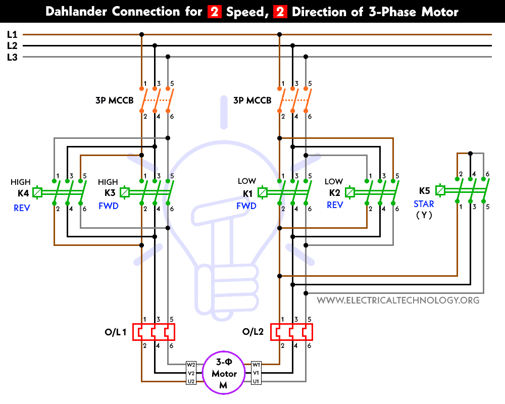
In the Dahlander connection, the motor has two separate sets of windings: a high-speed winding and a low-speed winding. These windings are connected to different voltage taps on the power supply. Keep in mind that K1 with K2 and K3 with K4 is connected with a phase changed respectively for reversing the direction of motor.
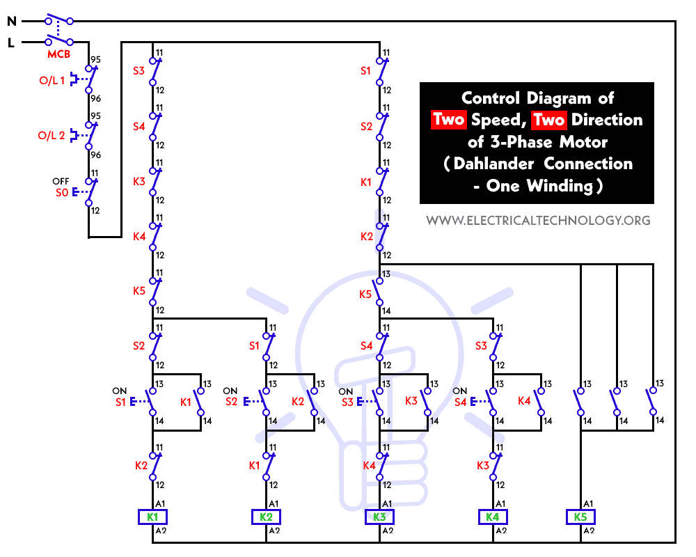
Control Diagram
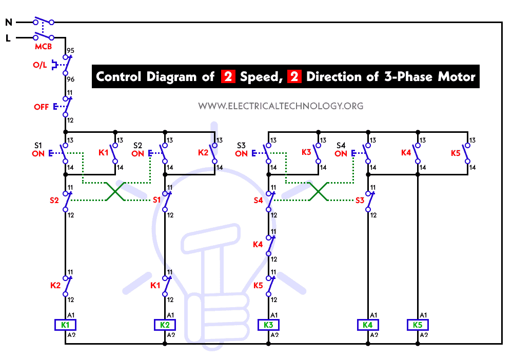
Control Circuit Diagram for Dahlander Connection
Working & Operation
Control & Operation of Two-Speed & Two Directions
Low Speed – Clockwise Direction
- When the start pushbutton is pressed, contactor K1 is energized, leading to the closing of the open contacts and resulting in the motor starting at low speed in the clockwise direction.
High Speed – Clockwise Direction
- By using the changeover, K1 is de-energized by the opening of the closed contacts of S3.
- This way, both contactors K5 (Star) and K3 are energized by the closing of the normally open contacts of S3.
- This is only possible (for K5) when the normally closed contacts of K1 are closed due to interlocking. Similarly, K3 is only energized when the normally open contacts of K5 change their state from Open to Closed.
- During this time, the motor runs at high speed.
- If the operator needs to operate the motor back at low speed, the above process should be reversed, i.e., they need to use the changeover switch again and select the low speed.
High Speed – Anticlockwise Direction
- When K3 is de-energized by the opening of the normally closed contacts of S4, simultaneously, contactor K4 is energized by the closing of the normally open contacts of S4, which leads to the motor running at high speed in the anticlockwise direction.
- Due to interlocking, K4 only energizes when the normally closed contacts of K3 are closed.
Low Speed – Anticlockwise Direction
- The process of changing to low speed is the same as above, except for activating the S2 contacts.
- When the operator presses the OFF pushbutton (S0), all five contactors de-energize, leading to the switch-off of the 3-phase motor.
Related Posts:
- Star-Delta (Y-Δ) 3-phase Motor Starting Method by Automatic star-delta starter with Timer.
- Three Phase Motor Connection STAR/DELTA Without Timer – Power & Control Diagrams
- Three Phase Motor Connection Star/Delta (Y-Δ) Reverse / Forward with – Timer Power & Control Diagram
- Starting & Stopping of 3-Phase Motor from more than One Place Power & Control diagrams
- Control 3-Phase Motor from more than Two buttons – Power & Control Diagrams
- ON / OFF Three-Phase Motor Connection Power & Control Schematic and Wiring Diagrams
- Three Phase Motor Connection Reverse and Forward – Power and Control wiring diagrams
- Three Phase Slip Ring Rotor Starter – Control & Power Diagrams
- Even Motor Power & Control Circuit Diagrams for 3-Phase Motor


i love it
very nice & educative
Very good.. Perfect..
I want an online supervisor. I want to do a project on control circuits
hi dears
i didn’t understand , there is 4 double push-button in control diagram , but in control box there is only 2 push button that i don’t know about inside circuit of it , please help me!
good job
So have a question.
I wired a 2 speed 3 phase motor with a rotary cam 6 stage switch. So this allows for forward and reverse with low and high speed. Now the problem I have is that if you select forward low speed the motor runs in the correct direction but when I select forward high speed the motor runs with the higher speed but in reverse.
Tried switching phases but on the supply and between the motor windings but low and high speed always turns the opposite direction.