
How to Find the Right Size Capacitor Bank Value in both kVAR and Microfarads for Power Factor Correction – 3 Methods
As we got lots of emails and messages from the audience to make a step by step tutorial which shows how to calculate the proper size of a capacitor bank in kVAR and micro-farads for power factor correction and improvement in both single phase and three phase circuits.
This article will show how to find the right size capacitor bank in both Microfarads and kVAR to improve the existing “i.e. lagging” P.F to the targeted “i.e. desired” as corrected power factor has multiple advantages. Below, we showed three different methods with solved examples to determine the exact value of capacitance of a capacitor for P.F correction.
Now let’s begin and consider the following examples…
How to Calculate the Capacitor Value in kVAR?
Example: 1
A 3 Phase, 5 kW Induction Motor has a P.F (Power factor) of 0.75 lagging. What size of Capacitor in kVAR is required to improve the P.F (Power Factor) to 0.90?
Solution #1 (Simple Method using the Table Multiplier)
Motor Input = 5kW
From Table, Multiplier to improve PF from 0.75 to 0.90 is 0.398
Required Capacitor kVAR to improve P.F from 0.75 to 0.90
Required Capacitor kVAR = kW x Table 1 Multiplier of 0.75 and 0.90
= 5kW x 0.398
= 1.99 kVAR
And Rating of Capacitors connected in each Phase
= 1.99kVAR / 3
= 0.663 kVAR
Solution # 2 (Classic Calculation Method)
Motor input = P = 5 kW
Original P.F = Cosθ1 = 0.75
Final P.F = Cosθ2 = 0.90
θ1 = Cos-1 = (0.75) = 41°.41; Tan θ1 = Tan (41°.41) = 0.8819
θ2 = Cos-1 = (0.90) = 25°.84; Tan θ2 = Tan (25°.50) = 0.4843
Required Capacitor kVAR to improve P.F from 0.75 to 0.90
Required Capacitor kVAR = P (Tan θ1 – Tan θ2)
= 5kW (0.8819 – 0.4843)
= 1.99 kVAR
And Rating of Capacitors connected in each Phase
1.99 kVAR / 3 = 0.663 kVAR
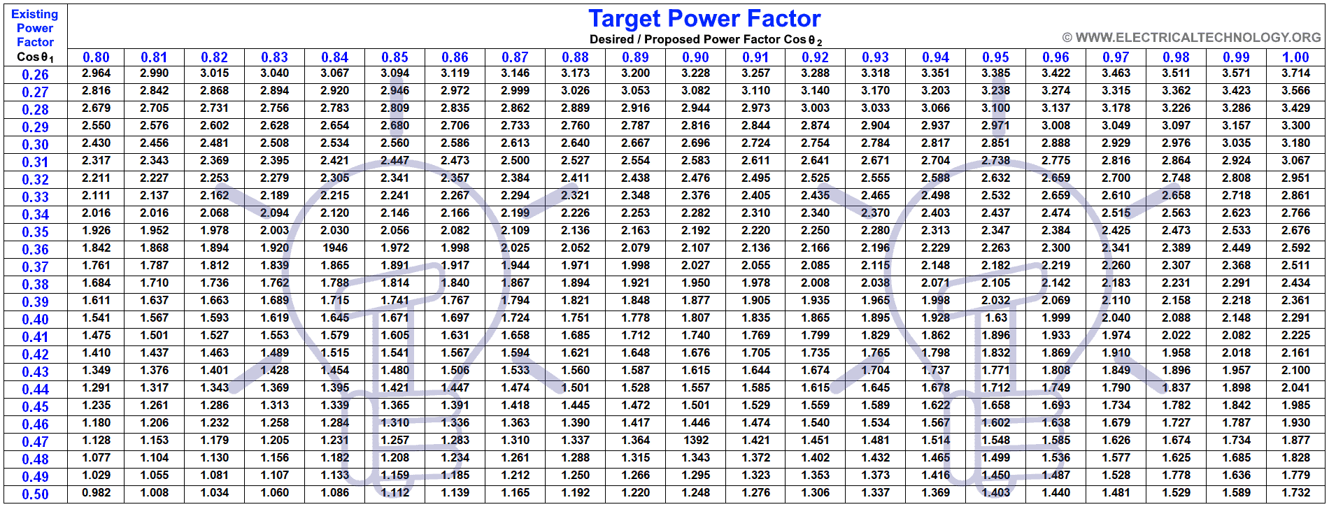
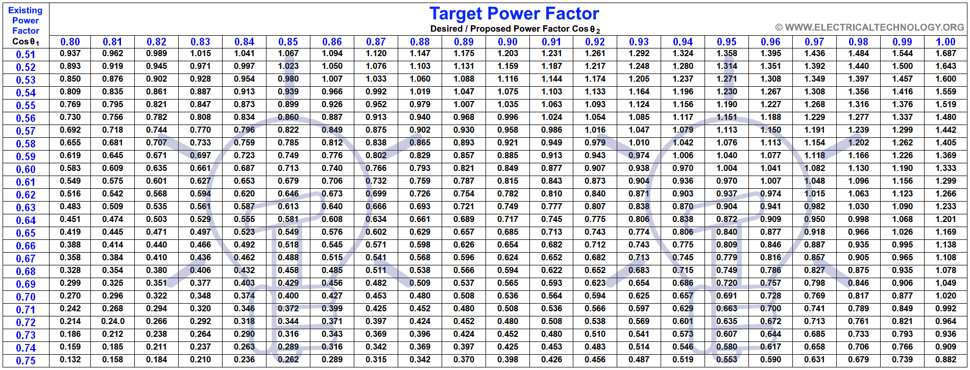
Note: Tables for Capacitor Sizing in kVAr and microfarads for PF Correction
The following tables (given at the end of this post) have been prepared to simplify kVAR calculation for power factor improvement. The size of capacitor in kVAR is the kW multiplied by factor in table to improve from existing power factor to proposed power factor. Check the others solved examples below.
Example 2:
An Alternator is supplying a load of 650 kW at a P.F (Power factor) of 0.65. What size of Capacitor in kVAR is required to raise the P.F (Power Factor) to unity (1)? And how many more kW can the alternator supply for the same kVA loading when P.F improved.
Solution #1 (Simple Table Method using Table Multiple)
Supplying kW = 650 kW
From Table 1, Multiplier to improve PF from 0.65 to unity (1) is 1.169
Required Capacitor kVAR to improve P.F from 0.65 to unity (1).
Required Capacitor kVAR = kW x Table 1 Multiplier of 0.65 and 1.0
= 650kW x 1.169
= 759.85 kVAR
We know that P.F = Cosθ = kW/kVA . . .or
kVA = kW / Cosθ
= 650/0.65 = 1000 kVA
When Power Factor is raised to unity (1)
No of kW = kVA x Cosθ
= 1000 x 1 = 1000kW
Hence increased Power supplied by Alternator
1000kW – 650kW = 350kW
Solution # 2 (Classic Calculation Method)
Supplying kW = 650 kW
Original P.F = Cosθ1 = 0.65
Final P.F = Cosθ2 = 1
θ1 = Cos-1 = (0.65) = 49°.45; Tan θ1 = Tan (41°.24) = 1.169
θ2 = Cos-1 = (1) = 0°; Tan θ2 = Tan (0°) = 0
Required Capacitor kVAR to improve P.F from 0.75 to 0.90
Required Capacitor kVAR = P (Tan θ1 – Tan θ2)
= 650kW (1.169– 0)
= 759.85 kVAR
How to Calculate the Capacitor Value in Microfarad & kVAR?
The following methods show that how to determine the required capacitor bank value in both kVAR and Micro-Farads. In addition, the solved examples also show that how to convert the capacity of a capacitor in microfarad to kVAR and kVAR to microfarad for P.F. This way, a right size capacitor bank can be installed in parallel to each phase load side to obtain the targeted power factor.
Example: 3
A 500 volts 60 c/s single phase motor takes a full load current of 50 amp at P.F 0.86 lagging. The motor power factor has to be improved to 0.94 by connecting capacitor bank across it. Calculate the required capacity of capacitor in both kVAR and μ-Farads?
Solution:
(1) To find the required capacity of Capacitance in kVAR to improve P.F from 0.86 to 0.94 (Two Methods)
Solution #1 (Table Method)
Motor Input = P = V x I x Cosθ
= 500V x 50A x 0.86
= 21.5kW
From Table, Multiplier to improve PF from 0.86 to 0.94 is 0.230
Required Capacitor kVAR to improve P.F from 0.86 to 0.94
Required Capacitor kVAR = kW x Table Multiplier of 0.86 and 0.94
= 21.5kW x 0.230
= 4.9 kVAR
Solution # 2 (Calculation Method)
Motor Input = P = V x I x Cosθ
= 500V x 50A x 0.86
= 21.5kW
Actual or existing P.F = Cosθ1 = 0.86
Required or target P.F = Cosθ2 = 0.94
θ1 = Cos-1 = (0.86) = 30.68°; Tan θ1 = Tan (30.68°) = 0.593
θ2 = Cos-1 = (0.95) = 19.94°; Tan θ2 = Tan (19.94°) = 0.363
Required Capacitor kVAR to improve P.F from 0.86 to 0.95
Required Capacitor kVAR = P in kW (Tan θ1 – Tan θ2)
= 21.5kW (0.593 – 0.363)
= 4.954 kVAR
(2) To find the required capacity of Capacitance in Farads to improve P.F from 0.86 to 0.97 (Two Methods)
Solution #1 (Table Method)
We have already calculated the required Capacity of Capacitor in kVAR, so we can easily convert it into Farads by using this simple formula
Required Capacity of Capacitor in Farads/Microfarads
- C = kVAR / (2π x f x V2) in Farad
- C = kVAR x 109 / (2π x f x V2) in Microfarad
Putting the Values in the above formula
= (4.954 kVAR) / (2 x π x 60Hz x 5002V)
= 52.56 μF
Solution # 2 (Calculation Method)
kVAR = 4.954 … (i)
We know that;
IC = V / XC
Whereas XC = 1 / 2π x f x C
IC = V / (1 / 2π x f x C)
IC = V x 2π x f x C
= (500V) x 2π x (60Hz) x C
IC = 188495.5 x C
And,
kVAR = (V x IC) / 1000 … [kVAR = ( V x I) / 1000 ]
= 500V x 188495.5 x C
IC = 94247750 x C … (ii)
Equating Equation (i) & (ii), we get,
94247750 x C = 4.954 kVAR x C
C = 4.954 kVAR / 94247750
C = 78.2 μF
Example 4
What value of Capacitance must be connected in parallel with a load drawing 1kW at 70% lagging power factor from a 208V, 60Hz Source in order to raise the overall power factor to 91%.
Solution:
You can use either Table method or Simple Calculation method to find the required value of Capacitance in Farads or kVAR to improve Power factor from 0.71 to 0.97. So We used the table method in this case.
P = 1000W
Actual Power factor = Cosθ1 = 0.71
Desired Power factor = Cosθ2 = 0.97
From Table, Multiplier to improve PF from 0.71 to 0.97 is 0.741
Required Capacitor kVAR to improve P.F from 0.71 to 0.97
Required Capacitor kVAR = kW x Table Multiplier of 0.71 and 0.97
= 1kW x 0.741
= 741 VAR or 0.741 kVAR (required Capacitance Value in kVAR)
Current in the Capacitor =
IC = QC / V
= 741kVAR / 208V
= 3.56A
And
XC = V / IC
= 208V / 3.76 = 58.42Ω
C = 1/ (2π x f x XC)
C = 1 (2π x 60Hz x 58.42Ω)
C = 45.4 μF (required Capacitance Value in Farads)
Capacitor kVAR to μ-Farad & μ-Farad to kVAR Conversion
The following formulas are used to calculate and convert capacitor kVAR to Farads and Vice Versa.
Required Capacitator in kVAR
Convert Capacitor Farads & Microfarads in VAR, kVAR and MVAR.
- VAR = C x 2π x f x V2x 10-6 … VAR
- VAR = C in μF x f x V2 / (159.155 x 10³) … in VAR
- kVAR = C x 2π x f x V2 x 10-9 … in kVAR
- kVAR = C in μF x f x V2 ÷ (159.155 x 10⁶) … in kVAR
- MVAR = C x 2π x f x V2 x 10-12 … in MVAR
- MVAR = C in μF x f x V2 ÷ (159.155 x 10⁹) … in MVAR
Required Capacitor in Farads/Microfarads.
Convert Capacitor kVAR in Farads & Microfarads
- C = kVAR x 103 / 2π x f x V2 … in Farad
- C = 159.155 x Q in kVAR / f x V2 … in Farad
- C = kVAR x 109 / (2π x f x V2) … in Microfarad
- C = 159.155 x 10⁶ x Q in kVAR / f x V2 … in Microfarad
Where:
- C = Capacitance in Microfarad
- Q = Reactive Power in Volt-Amp-Reactive
- f = Frequency in Hertz
- V = Voltage in Volts
Good to Know:
Following are the important electrical formulas used in Power factor improvement calculation.
Active Power (P) in Watts:
- kW = kVA x Cosθ
- kW = HP x 0.746 or (HP x 0.746) / Efficiency … (HP = Motor Horse Power)
- kW = √ ( kVA2 – kVAR2)
- kW = P = V x I Cosθ … (Single Phase)
- kW = P = √3x V x I Cosθ … (Three Phase Line to Line)
- kW = P = 3x V x I Cosθ … (Three Phase Line to Phase)
Apparent Power (S) in VA:
- kVA = √(kW2 + kVAR2)
- kVA = kW / Cosθ
Reactive Power (Q) in VA:
- kVAR = √(kVA2 – kW2)
- kVAR = C x (2π x f x V2)
Power Factor (from 0.1 to 1)
- Power Factor = Cosθ = P / V I … (Single Phase)
- Power Factor = Cosθ = P / (√3x V x I) … (Three Phase Line to Line)
- Power Factor = Cosθ = P / (3x V x I) … (Three Phase Line to Neutral)
- Power Factor = Cosθ = kW / kVA … (Both Single Phase & Three Phase)
- Power Factor = Cosθ = R/Z … (Resistance / Impedance)
And
- XC = 1 / (2π x f x C) … (XC = Capacitive reactance)
- IC = V / XC … (I = V / R)
Related Posts:
Capacitor Bank Sizing & PF Correction Calculators
If the above two methods seem a little bit tricky (which should not at least), you may then use the following online power factor kVAR and microfarads calculators made by our team for you.
- μ-Farad to kVAR Calculator
- kVAR to Farad Calculator
- Capacitor Bank in kVAR & µF Calculator
- Power Factor Correction Calculator – How to Find P.F Capacitor in µF & kVAR?
- How to Convert Capacitor μ-Farads to kVAR and Vice Versa? For P.F Correction
Capacitor Sizing Chart & Table for Power Factor Correction
The following power factor correction chart can be used to easily find the right size of capacitor bank for desired power factor improvement. For example, if you need to improve the existing power factor from 0.6 to 0.98, just look at the multiplier for both figures in the table which is 1.030. Multiply this number with the existing active power in kW. You can find the real power by multiplying the voltage to the current and the existing lagging power factor i.e. P in Watts = Voltage in volts x Current in Amps x Cosθ1. This easy way, you will find the required value of capacitance in kVAR which is needed to get the desired power factor.
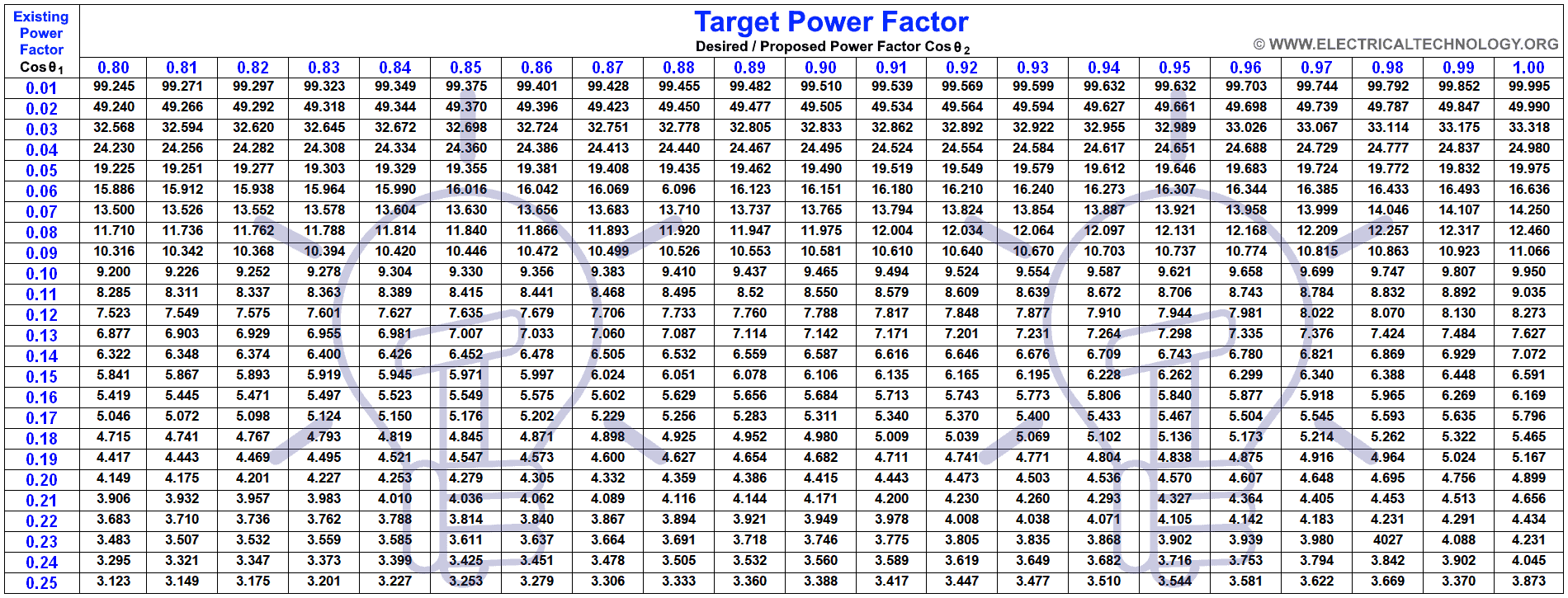
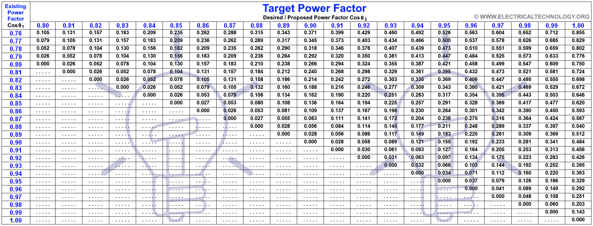
Here is the whole table if you need it to download as a reference.

Related Posts
- Power Factor improvement Methods with Their advantages & Disadvantages
- How to calculate the value of resistor for LED’s (with different types of LED’s circuits)
- How to Calculate the Rating of Transformer in kVA (1 Phase and 3 Phase)?
- How To Calculate Your Electricity Bill. Easy Explanation with Calculator
- How to Find The Suitable Size of Cable & Wire for Electrical Wiring Installation (SI & Metric)
- How to Find the Proper Size of Circuit Breaker? Breaker Calculator & Examples
-
 Should You Connect GND and 0VDC? Combined AC & DC Grounding
-
 Can you Combine AC and DC Ground in a Solar Installation?
-
 Why Doesn’t DC System Require a Grounding System Similar to AC System?
-
 Why are Capacitors Connected in Series in Power Lines?
-
 Why is a Capacitor Bank Connected in Parallel and Not in Series for P.F?
-
 How to Calculate the Floor Area For General Lighting?