
How to Determine the Suitable Size of Wire and Cable or Electrical Wiring Installation? Examples in Imperial and Metric Systems Based on NEC, IEC and IEEE.
The following step-by-step guide will show you how to calculate the correct size of cable and wire, or any other conductor, for electrical wiring installations with solved examples in both British or English and SI Systems, i.e., Imperial and Metric Systems, respectively.
Keep in mind that selecting the proper wire size is crucial when sizing a wire for electrical installations. An inappropriate size of wire for larger loads with high current may lead to chaos, resulting in the failure of electrical equipment, hazardous fires, and serious injuries.
This step-by-step guide explains how to calculate the correct wire and cable size for electrical wiring installations. We will use examples in both the British/English and SI systems (Imperial and Metric systems, respectively). The solved examples for wire sizing are based on wire ampacities and current-carrying capacities according to NEC, IEC 60364, 60228, 60898-1, 60947-2 (International Standards), IET Wiring Regulations, BS 7671 (British Standards), and IEEE regulations.
- Related Post: How to Size Service-Entrance Conductors and Cables?
Why is Correct Wire Size Important?
Selecting the correct wire size is crucial when planning and sizing conductors for electrical installations. Using an improper wire size for high-current loads can lead to equipment failure, hazardous fires, and serious injuries.
using correct wire size is crucial in electrical wiring installations for several key reasons:
Safety
Undersized wires can overheat due to excessive current flow, which may lead to electrical fires or equipment damage. Choosing the correct wire size ensures that the wire can handle the expected load without overheating or failing.
Current-Carrying Capacity
Each wire gauge has a specific current-carrying capacity, known as ampacity. Using the proper wire size ensures that the wire can handle the required current without generating excessive heat or voltage drop, ensuring the efficient operation of electrical equipment.
Voltage Drop
Incorrect wire sizing can lead to excessive voltage drop, where electrical power is lost as heat along the wire. This can reduce the efficiency of appliances and lighting, cause motors to underperform, and increase energy consumption. Proper wire sizing minimizes voltage drop and ensures that the correct voltage reaches the end of the circuit.
Compliance with Standards
Electrical codes and standards, such as the NEC, IEC, and BS 7671, specify minimum wire sizes for different applications. Following these regulations ensures that installations are legal, safe, and meet industry standards.
Longevity of the Installation
Correctly sized wires have a longer lifespan because they are less likely to suffer from excessive heat, wear, or mechanical stress. This reduces maintenance costs and the need for early replacements.
Cost Efficiency
While undersized wires pose safety risks, oversizing wires can lead to unnecessary costs. Proper wire sizing strikes a balance between safety, performance, and cost.
Factors Affecting the Wire Size
- Current Carrying Capacity: The amount of current the wire needs to carry (known as ampacity) influences its size, ensuring it can handle the load without overheating.
- Load Current and Breaker Size: The known value of load current in amperes and the rating of circuit breaker.
- Voltage Drop: For longer distances, consideration of voltage drop becomes crucial to maintain the efficiency and proper functioning of the electrical system.
- Ambient Temperature: The environmental temperature affects the wire’s ability to dissipate heat, impacting its current-carrying capacity.
- Insulation Type: Different insulating materials have varying thermal and electrical properties, influencing the overall performance and size requirements.
- Installation Method: The manner in which the wire is installed, whether in conduit, cable trays, or exposed, can affect its ability to dissipate heat and, consequently, its size.
- Conductor Material: Copper and aluminum have different conductivity and temperature characteristics, influencing their suitability for specific applications and, consequently, their sizing.
- Code Guidelines: Adherence to electrical codes and standards is crucial, as they provide specifications and regulations for wire sizing to ensure safety and compliance.
- Type of Load: The nature of the electrical load, whether resistive, inductive, or capacitive, can impact the wire size needed for optimal performance.
- Cable Bundling: When multiple conductors are bundled together, there is a need to derate the ampacity of each conductor, affecting the overall wire size requirements.
- Frequency of Operation: For applications involving alternating current (AC), the frequency of operation can influence the skin effect, affecting the effective resistance and thus impacting wire sizing.
- Types of Cables: It also depends on types of wires and cables for copper and aluminum such as NM-B (Non-Metallic Sheathed Cable) also known as Romex, MC Metal-clad Cables, THHN/THWN, UF-B (Underground Feeder), USE (Underground Service Entrance), SE (Service Entrance):
Related Post: How to Size a Branch Circuit Conductors with Protection?
Voltage Drop in a Cables
All conductors have resistance, which is directly proportional to their length and inversely proportional to their diameter:
R ∝ l/a … [Ohm’s laws of resistance R = ρ (L÷ a)]
As current flows through a conductor, a voltage drop occurs. While it can be neglected for short distances, longer or thinner wires require voltage drop considerations to ensure proper system function.
According to NEC 210.19(A), the maximum recommended voltage drop on a branch circuit is 3% and from the beginning of a feeder to the farthest outlet on a branch circuit should not exceed 5% (215.2(A). For long-distance runs over 50 feet(15.25 meters), consider upgrading to a larger gauge wire to compensate for voltage drop. According to NEC 310-16, for every 100 feet (30.50 meters) of wire length, add 20% ampacity to account for voltage drop.
The IEEE B-23 rule specifies that voltage drop should not exceed 2.5% of the supply voltage.
According to BS 7671 – TABLE 4Ab and IEC60364-5-52, article 525, table G.52.1, the limit of maximum voltage drop for lighting circuits is 3% and 5% of other heating and power usage supplied by public LV distribution system. In case of private LV supply system, the voltage drop for lighting and other HVAC systems is 6% and 8% respectively. If the voltage drop exceeds the limits, larger conductor (cable and wires) must be used to compensate the condition.
According to AS3008, the standard allowable voltage drop from the supply to any point in the circuit should not exceed 5% (AS/NZS 3008). However, an exception is made when a low-voltage substation is installed on the premises and used as a dedicated circuit. In this case, the allowable voltage drop can increase to 7%, as per AS3000.
Example:
If the supply voltage is 230V AC, then the value of allowable voltage drop should be;
Allowable Voltage Drop = 230 (2.5/100) = 5.75V
Similarly, if the supply voltage is 120V AC, the allowable voltage drop should be no more than 3.6V for a separate branch circuit (120V × 3% = 3.6V) and 6V for feeder and branch circuits (120V × 5% = 6V). Refer to NEC Code 210.19(A) and 215.2(A), and Table 310-16, which states that 20% additional ampacity for every 100 feet of distance should be added to counter the voltage drop in the circuit.
In electrical wiring circuits, voltage drops also occur from the distribution board to the various sub-circuits and final sub-circuits. For sub-circuits and final sub-circuits, the allowable voltage drop should be half of the general allowable voltage drop (i.e., 2.75V of 5.5V as calculated above).
Normally, voltage drop tables describe voltage drop in Amperes per meter (A/m), such as the voltage drop in a one-meter cable carrying one Ampere of current.
There are two methods to define voltage drop in a cable, which we will discuss below.
- For SI System (Metric): Voltage drop is defined in terms of per amp per meter.
- For FPS System (Imperial): Voltage drop is defined in volts per ampere per 100 feet (30 m) based on circuit run i.e. distance and length of wire.
Related Post: How to Find the Right Wire Size for 100A Service 120V/240V Panel?
Finding Voltage Drop in the Cable
To find the voltage drop in a cable for this tutorial, follow the simple steps below:
- First, find the maximum allowable voltage drop from the give tables.
- Next, determine the load current.
- According to the load current, select an appropriate cable (whose current rating is nearest to the calculated load current) from Table 1.
- From Table 1, find the voltage drop per meter or per 100 feet (depending on your preferred system) according to its rated current.
Now, calculate the voltage drop for the actual length of the wiring circuit based on its rated current using the following formulas:
- (Actual length of circuit × voltage drop per meter) / 100 = Voltage drop per meter.
- (Actual length of circuit × voltage drop per 100 feet) / 100 = Voltage drop per 100 feet.
Next, multiply the calculated voltage drop by the load factor, where:
Load factor = Load current / Rated current of the cable (from the table).
It will show the exact value of voltage drop in the cable when load current is flowing through it.
- If the calculated voltage drop is less than the maximum allowable voltage drop (step 1), then the selected cable size is correct.
- If the calculated voltage drop is greater than the maximum allowable voltage drop (step 1), calculate the voltage drop for the next larger cable size. Continue this process until the calculated voltage drop is less than the maximum allowable voltage drop from step 1.
You may use voltage drop calculator or manual methods using different voltage drop formulas to determine voltage drop and wire size. If the calculated voltage drop is less than the maximum allowable drop, the cable size is appropriate. If it is greater, select the next larger cable size.
- Related Post: How to Size Equipment Grounding Conductor (EGC)?
How to Determine the Correct Size of Cable & Wire for a Given Load?
Below are solved examples demonstrating how to find the proper cable size for a given load.
For a given load, cable size may be determined using various IEC and NEC tables (such Article 310 – Table – 310.15 (B) 16. However, it is crucial to keep in mind the role of ambient temperature and voltage drop for distance between main panel and subpanel.
When determining the size of cable for a given load, take into account the following general rules of thumbs.
- For a given load, apart from the known current value, there should be a 20% additional margin as safety factor for continuous load circuits and for future or emergency needs (required by both NEC and IEC/IEEE).
- In the NEC – 310-16, add an additional 20% ampacity to the wire size if the length of the wire exceeds 100 ft (between the main panel and the subpanel).
- In IEC, the voltage drop should be limited to 1.25%, and for the final sub-circuit, the voltage drop should not exceed 2.5% of the supply voltage from the energy meter to the distribution board.
- Consider the change in temperature, which affects the ampacity (current carrying capacity) of the wire. When needed, use the temperature factor (also known as Correction factors or Rating Factors) given in Table 3, Table 6 and related NEC table given at the end of this article).
- Additionally, take the load factor (diversity factor or demand factor (NEC – 220.42 and (220.45)) into consideration when determining the size of the cable.
- When calculating the cable size, consider the ambient temperature and type of wiring system; for example, in an open wiring system, temperature would be low, but in conduit wiring, temperature increases due to the absence of air.
Related Post: How to Size Grounding Electrode Conductor (GEC)?
Solved Examples of Proper Cable & Wire Size
The following examples illustrate how to determine the proper size of cables for electrical wiring installations. These examples will make it easy to understand the method of determining the proper cable size for a given load in both single phase ad three phase wiring installations.
Good to Know: It is recommended to use the correct Wiring Color Codes for installation based on NEC and IEC 60445:2021.
Example 1 – (Imperial System Followed by NEC)
What is the correct wire size for a 1,920W load circuit supplied by 120V AC at 60°C (140°F)?
Solution:
First of all, let’s determine the load current in amperes using basic Ohm’s Law that will flow from the 120V breaker to the 1.92kW load.
I (in Amps) = P (in Watts) ÷ V (in Volts)
I = 1,920 W ÷ 120 V
I = 16 Amp
Now, add a safety factor of 1.25 (based on 125% rule also known as continuous load rule), as per NEC 210.20(A) for branch circuits, feeders, and service loads. This code specifies that only 80% of the branch circuit load should be connected to the circuit for the ampacity of the wire for any load.
In other words, the breaker should handle 125% of the rated load current amps. For instance, a 15-ampere breaker should be used for a 12-ampere load point. This way:
I = 16 amp 1.25
or 16 amp 125%
I = 20 Amp.
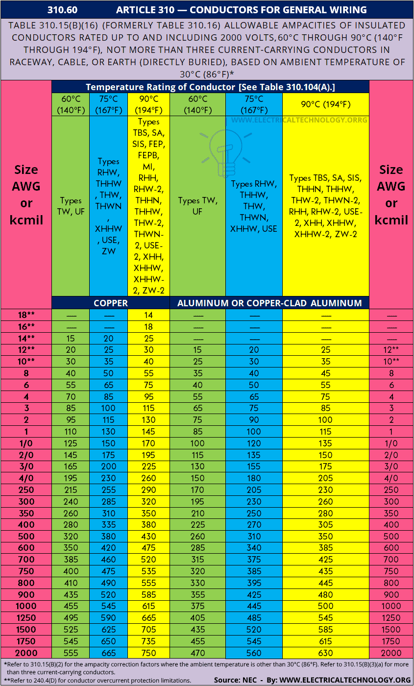
Now, If you see in the AWG wire size chart and NEC Table 310-15B (16) Article 310.60 (given below), the right size for 20 amp circuit is #12 AWG copper or #10 AWG aluminum.
Good to Know:
According to 240.4(D), you are permitted to use:
- 14 AWG copper for 15 amperes breaker and outlets
- 12 AWG copper 20 for amperes breaker and load circuits
- 10 AWG copper 30 for amperes OCPD and load points
Related Post: How to Size a Load Center, Panelboards and Distribution Board?
Example 2 – (240V and Distance Involved – NEC)
Find the Proper wire size for 2,400 W load circuit supplied by 240V single phase at a distance of 100 feet?
Solution:
Find the current using the following formula (same as mentioned above)
Current = Power ÷ Voltage
I = 2,400 W ÷ 240 V
I = 10 Amperes
Now, multiply the safety factor of 1.25 (80% of load should be connected of the rated ampacity) to the calculated amperage. The same applies to the breaker size and outlet rating.
As the circuit is 100ft away, add additional 20% ampacity to the calculated value (according to the NEC Code – 310-16) to counter the voltage drop in the circuit.
Total Amps = 12.5A + 2.5A = 15 Amperes.
According to NEC table 310-15B and AWG wire size chart, the suitable wire size for 15 amp circuit is #14 AWG copper at 60°C (140°F) and #12 AWG aluminum.
Notes:
- NEC Table 310.16 with the help of 240.4(A) through (G) which shows the 14 AWG wire size is able to carry 15A at 60°C (140°F) and 20A at 75°C (167°F).
- The determined wire size, breaker rating, and ampacity in the above calculation for North America and Canada comply with the National Electrical Code (NEC) – Sections 210.19(A), 215.2, and 230.42(A) for continuous and non-continuous loads and 110.14(C) for ambient temperature rating.
- This calculation are based on the NEC guidelines. For more details, refer to NEC 210.21, 210, 24, 220.110, 220.14, 220.42, 220.45, 220.53, 220.55, 310-14 and 517.22.
Related Posts: How to Determine the Right Size Capacity of a Subpanel?
Warning:
- #14 AWG can safely handle 15-amp at 60°C (140°F) and 20-amp at 75°C (167°F).
- #14 AWG can be used for maximum of 15-Amp of non-continuous load circuit and maximum of 12-Amp of continuous load circuits (no more than 80% of the load should be connected to the rated of 15A circuit breaker).
- It is against the code to use lower size of wire than the recommended.
- It is always advisable to use copper wire instead of aluminum for better conductivity and reduced power consumption. If it is necessary to use aluminum, the wire size in AWG may differ compared to a copper conductor. Refer to the tables given below to select the wire size accordingly in the case of using aluminum.
- In addition, it is recommended to use solid wire instead of stranded wire for a better grip, reduced sparks, and a protected environment from shock and fire.
Example 3 – (BS 7671 (British Standards) in Imperial – IEC)
Note: Example 3 is based on BS-7671 (first published in 1992) for old Imperial, British or English System – IEC. It was used prior 2004 when the BSI adopted the IEC 60445 / 60446 standard and the IEE wiring regulations. In this example, Tables 1 to 5 are used to find the right wire size for this system.
Example: For an electrical wiring installation in a building, where the total load is 5kW and the total length of cable from the energy meter to the sub-circuit distribution board is 35 feet, with a supply voltage of 230V and a temperature of 40°C (104°F), find the most suitable size of cable if wiring is installed in conduits.
Solution:
- Total Load = 5kW = 5 1,000W = 4,500W
- 20% additional load = 5,000 (20/100) = 1,000W
- Total Load = 5000W + 1,000W = 5,400W
- Total Current = I = P ÷ V = 6,000W /230V = 26.08A
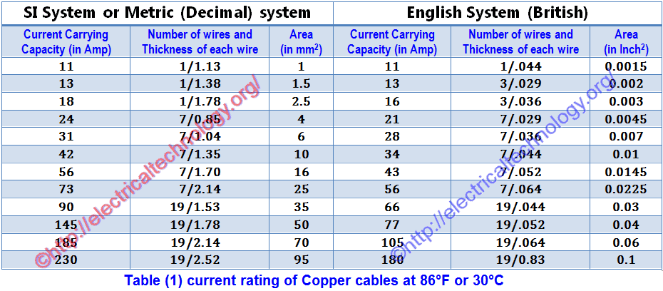
Now select the size of cable for load current of 26.08A (from Table 1 on the right side) which is 7/0.036″ (28 Amperes). It means we can use 7/0.036″ (4 mm2) cable according to table 1.
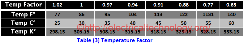
Now, check the selected (7/0.036″) cable with the temperature factor in Table 3. The temperature factor is 0.94 (from Table 3) at 40°C (104°F), and the current carrying capacity of (7/0.036″) is 28A. Therefore, the current carrying capacity of this cable at 40°C (104°F) would be:
Current rating for 40°C (104°F) = 28 0.94 = 26.32 Amp.
Since the calculated value (26.32 Amp) at 40°C (104°F) is less than the current carrying capacity of the (7/0.036″) cable, which is 28A, this size of cable 4 mm2 (7/0.036″) is also suitable with respect to temperature.
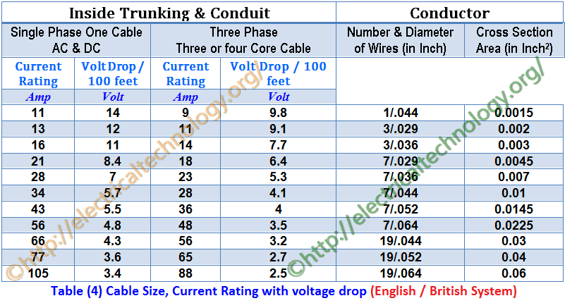
Now find the voltage drop for 100 feet for this (7/0.036″) cable from Table 4 which is 7V, But in our case, the length of cable is 35 feet. Therefore, the voltage drop for 35 feet cable would be;
Voltage Drop = Vd L
Actual Voltage drop for 35 feet = (7V 35/100) (26.08A/28A) = 2.28V
And Allowable voltage drop = 3% 230V = 6.9V
Here, the actual voltage drop (2.28V) is less than the maximum allowable voltage drop of 6.9V. Therefore, the most appropriate and suitable cable size for that given load in the electrical wiring installation is (7/0.036″) which is equal to 4 mm2.
Example 4 – (BS 7671 (British Standards ) in Metric – 18th Ed.)
If the single-phase supply voltage is 230V AC, how do you calculate the circuit current and cable size for each sub-circuit and the main circuit for the following load to be connected in a residential building?
Sub-Circuit 1
- 2 lamps each o 800W and
- 3 fans each of 80W
- 4 TV each of 120W
Sub-Circuit 2
- 6 Lamps each of 80W and
- 5 sockets each of 100W
- 4 lamps each of 800W
Solution:
Total Load of Sub-Circuit 1
= (2 800W) + (3 80W) + (4 120W)
= 1,600W + 240W + 480W = 2,320W
Current for Sub-Circuit 1 = I = P/V = 2,320W/230V = 10A
Total Load of Sub-Circuit 2
= (4 80W) + (5 100W) + (6 500W)
= 320W + 500W + 3,000W= 3,820W
Current for Sub-Circuit 2 = I = P/V = 3,820W/230V = 16.6A
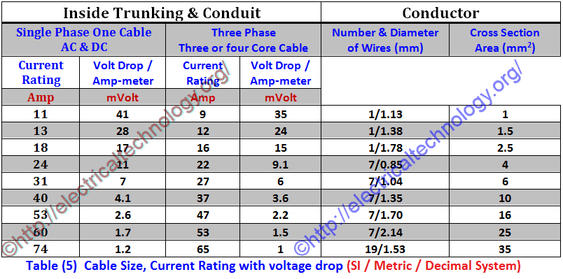
Therefore, Cable suggested for sub circuit 1 having 10A = 1 mm2 (13.5 Amp – Table 6 or Table 5) equivalent to 1/044″ or 3/.029″ (11A and 13 Amp respectively – Table – 4 ).
Cable suggested for Sub-Circuit 2 having 16.6A = 1.5 mm2 (17.5 Amp – Table 6) equivalent to 3/036″ or 7/.029″ (16A and 21 Amp respectively – Table – 4 ).
Total Current drawn by both Sub-Circuits = 10A + 16.6A = 26.6 A
Therefore, cable suggested for Main-Circuit having 26.6A = 4 mm2 (32 Amp – Table 6) equivalent 7/.044″ ( 34 Amp – Table – 4 ).
- 1mm2 twin and earth (T & E) cable size with 6A breaker is used for general lighting.
- 2.5mm2 twin and earth (T & E) cable size with 16A breaker is used for power circuits.
- 4mm2 twin and earth (T & E) cable size with 32A breaker is used for showers, water heaters and cookers.
Related Post: What is the Right Wire Size for a 4.8kW, 240V Range: #10 or #12?
Example 5 – (IEC 60364 in Metric System – IEC)
Note: Example 5 is based on IEC 60364 in Metric / SI / Decimal System. In this example, Tables 6-8 are used to find the correct wire size.
Example: What XLPE or EPR size of cable suits for given situation?
- Load = 4.5kW
- Volts = 230V AC – Single Phase
- Length of Circuit = 20 meter
- Temperature = 35°C (95°F)
Solution:
Load = 4.5kW = 4,500 W
Voltage = 230V
Current = I = P/V = 4.500W / 230V = 19.56A
Total Load Current = 19.56A
Now select the size of cable for load current of 19.56A (from Table 6) which is 2.5mm2 (having current capacity of 24 Amperes). Hence, we are allowed to use 2.5mm2 XLPE or EPR cable according to the table 6.
Now check the selected (2.5mm2) conductor with Correction factors or Rating Factors (Ca) for Ambient temperatures in Table 6. As the rating factor or correction factor is 0.96 (in table 6) at 35°C (95°F) for XLPE or EPR cable and current carrying capacity of (2.5mm2) is 24A, therefore, current carrying capacity of this cable at 40°C (104°F) would be;
Current rating for 35°C (95°F) = 24 0.96 = 23.04 Amp.
Since the calculated current (23.04A) at 35°C (95°F) is less than the current-carrying capacity of the 2.5mm² cable, which is 24 A, this cable size is suitable for the temperature conditions
Now find the voltage drop for per ampere meter for (2.5mm²) cable from (Table 8) which is 19mV, But in our case, the length of cable is 35 meter. Therefore, the voltage drop for 20 meter cable would be:
Actual Voltage drop for 35 meters =
= Vd I L
= 19 23.04A /1000) = 8.75V
And 5% Allowable voltage drop = (5 230V)/100 = 11.5V
Here the actual Voltage drop (8.75V) is less than that of maximum allowable voltage drop of 11.7V. Therefore, this is the correct size of cable conductor for that given load.
Example 6 – Three Phase Motor – IEC
A 10H.P (7.46kW) three phase squirrel cage induction motor of continuous rating using Star-Delta starting is connected through 400V supply by three single core PVC cables run in conduit from 250feet (76.2m) away from multi-way distribution fuse board. Its full load current is 19A. Average summer temperature in Electrical installation wiring is 35°C (95°F). Calculate the size of the cable for the induction motor?
Solution:
- Motor load = 10H.P = 10 746 = 7460W *(1H.P = 746W)
- Supply Voltage = 400V (3-Phase)
- Length of cable = 250feet (76.2m)
- Motor full load Current = 19A
- Temperature factor for 35°C (95°F) = 0.97 (From Table 3)
Now select the size of cable for full load motor current of 19A (from Table 5) which is 2.5mm2 (21A). *(Remember that this is a 3-phase system i.e. 3-core cable) and the voltage drop is 13.2V per km (Table 8). It means, we can use 2.5mm2 cable according Table (6).
Now check the selected (2.5mm2) cable with correction factor or rating factor in table (7), so the temperature factor is 0.94 and 0.96 for PVC an XPLE cables (in table 7) at 35°C (95°F) and current carrying capacity of (2.5mm2) is 21 Amperes for 3-phase, therefore, current carrying capacity of this cable at 40°C (104°F) would be:
Current rating for 35°C (95°F) = 21 0.96 = 20.16 Amp.
Since the calculated value (20.16 Amp) at 35°C (95°F) is less than that of current carrying capacity of (2.5mm2) cable which is rated for 21A, therefore this size of cable (2.5mm2) is suitable with the ambient and operating temperature.
Load factor = 19A/23A = 0.826
Now find the voltage drop for 76.2 m (250 feet) for this (2.5mm2) cable from table (8) which is 13.2V for three phase running motor at CosΦ 0.8. But in our case, the length of cable is 250 feet (76.2). Therefore, the voltage drop for this length would be;
Actual Voltage drop for 250 feet (76.2m) = (13.2 19A 76.2/1000) 0.826 = 15.78V
(15.78V÷ 400V) 100 = 3.9 %
This value is less than that authorized (8%) and is satisfactory.
And maximum 8% Allowable voltage drop = (8/100) 400V= 32V
Here the actual Voltage drop (15.78V) is less than that of maximum allowable voltage drop of 32V. Therefore, this is the right wire size for the given 3-phase load.
- Related Post: How to Size a Generator? Portable, Backup & Standby for Home & Commercial Applications
Wire CSA and Diameter Calculations
Wire Cross Section Area (CSA) Formulas
Wire Cross Sectional Area in kcmil (kilo circular mils)
An = 1000 × dn2 = 0.025 × 92(36-n)/19.5
Where;
- An = cross sectional area of “n” gauge wire size in kcmil.
- kcmil = kilo circular mils.
- n = the number of gauge size.
- d = wire square diameter in in2.
Wire Cross Sectional Area in Square Inches (in2).
An = (π/4)× dn2 = 0.000019635 × 92(36-n)/19.5
Where;
- An = cross sectional area of “n” gauge wire size in square inches (in2).
- n = the number of gauge size.
- d = wire square diameter in in2.
Wire Cross Sectional Area in kcmil (kilo circular mils)
An = (π/4) × dn2 = 0.012668 × 92(36-n)/19.5
Where;
- An = cross sectional area of “n” gauge wire size in square millimeters (mm2)
- n = the number of gauge size.
- d = wire square diameter in mm2.

Wire Diameter Calculation
-
Wire Diameter in Inches Formula
dn = 0.005 × 92(36-n)/39 …. In inches
Where “n” is number of the gauge size and “d” the wire diameter in inches.
-
Wire Diameter in mm (millimeters) Formula
dn = 0.127 × 92(36-n)/39 …. In millimeters (mm).
Where “n” is number of the gauge size and “d” the wire diameter in mm.
Wire Resistance Calculations Formula
(1). Rn = 0.3048 × 10⁹ × ρ / (25.42 × An)
Where;
- R = Resistance of the wire conductors (in Ω/kft).
- n = # of Gauge size.
- ρ = rho = resistivity in (Ω·m).
- An = the cross sectional area of n #gauge in square inches (in2).
Or;
(2). Rn = 109 × ρ/ An
Where;
- R = Resistance of the wire conductors (in Ω/km).
- n = # of Gauge size.
- ρ = rho = resistivity in (Ω·m).
- An = the cross sectional area of n #gauge in square millimeters (mm2).
Related Post: What is the Right Wire Size for 15A Breaker and Outlet?
Tables & Charts for Cable & Wire Sizes
Below are important tables and charts for current-carrying capacity, voltage drop, correction/rating factors, temperature ratings, etc. Using these tables are useful to determine the proper cable size for electrical wiring installations in both single-phase and three-phase supply systems.
Note: These tables are copyrighted by their respective institutions, including NEC, IEC, and IET, and are subject to future updates. Please ensure you are using the latest versions of the NEC and IEC regulations. If in doubt, consult a licensed electrician to ensure compliance with local codes and standards.
BS 7671 – IET & 60364 – IEC Tables
- Table 1 – Current rating of copper cables in mm2 and Inche2 at 30°C (86°F).
Click image to enlarge
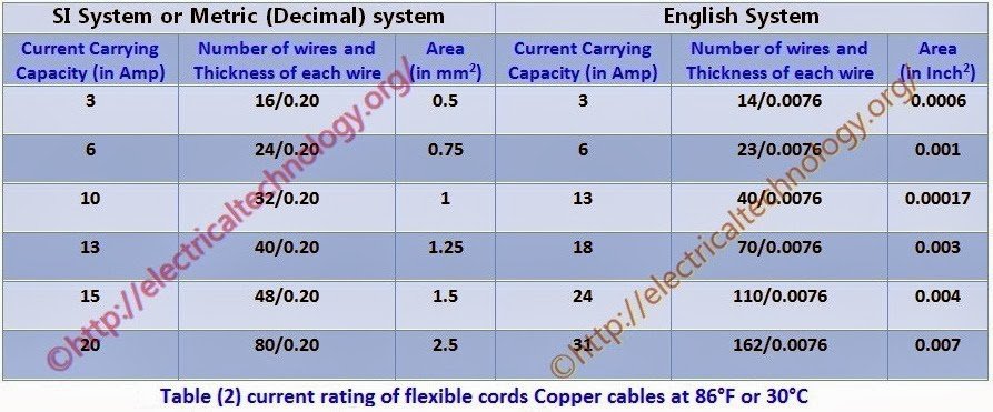
- Table 2 – Current rating of flexible cords – copper cables at 30°C (86°F).
Click image to enlarge
- Table 3 – Temperature factor
Click image to enlarge
- Table 4 – Cable Size in inches with current rating and voltage drop inside trucking and conduit.
Click image to enlarge
- Table 5 – Cable Size in mm2 with current rating and voltage drop inside trucking and conduit.
Click image to enlarge
- Table 6 – Current carrying capacity for 1-Phase and 3-Phase cables based on IEC 60364-5-52 – Table B.52.4 and BS 7671 – Table 4D1A.

- Table 7 – Correction factors or rating factors (Ca) based on IEC 60364-5-52 – Table B.52.14 and BS 7671 – Table 4B1

- Table 8 – Voltage drop values based on IEC 60364-5-52 and BS 7671 – Table 4E1B

- Table 9 – Size of Circuit Breaker and Conductor Selections for Different Domestic Circuits

- Table 10 – IEE Recommended Current Demands and Diversity Factors for Various Loads

- Table 11: Conductor and breaker size selection for domestic and residential application in 230V, single-phase AC circuits for IEC following countries.
- Table 12: Typical current carrying capacity of cables with suggested cable size, current rating in amps and recommended circuit breaker rating in amperes for 230V, single-phase AC circuits for IEC following countries.

NEC Wire Size Table 310.16 & Chart
NEC (National Electrical Code) Table 310.16 – ARTICLE 310 – Conductors for General Wiring & Allowable Ampacities of Conductors & Wire Sizes based on AWG (American Wire Gauge).
| Table 310.16 ARTICLE 310 — CONDUCTORS FOR GENERAL WIRING | |||||||
| NEC Table 310.16 – Allowable Ampacities of Insulated Conductors Rated Up to and Including 2000 Volts, for Temperatures Ranging from 60°C to 90°C (140°F to 194°F). Applicable to installations with no more than three current-carrying conductors in a raceway, cable, or directly buried in earth, based on an ambient temperature of 30°C (86°F). | |||||||
| Size AWG or kcmil | Temperature Rating of Conductor [See Table 310.4(1).] | Size AWG or kcmil | |||||
| 60°C (140°F) | 75°C (167°F) | 90°C (194°F) | 60°C (140°F) | 75°C (167°F) | 90°C (194°F) | ||
| Types TW, UF | Types RHW, THHW, THW, THWN, XHHW, USE, ZW | Types TBS, SA, SIS, FEP, FEPB, MI, RHH, RHW-2, THHN, THHW,
THW-2, THWN-2, USE-2, XHH, XHHW, XHHW-2, ZW-2 |
Types TW, UF | Types RHW, THHW, THW, THWN, XHHW, USE | Types TBS, SA, SIS, THHN, THHW,
THW-2, THWN-2, RHH, RHW-2, USE-2, XHH, XHHW, XHHW-2, ZW-2 |
||
| COPPER | ALUMINUM OR COPPER-CLAD ALUMINUM | ||||||
| 18** | — | — | 14 | — | — | — | — |
| 16** | — | — | 18 | — | — | — | — |
| 14** | 15 | 20 | 25 | — | — | — | — |
| 12** | 20 | 25 | 30 | 15 | 20 | 25 | 12** |
| 10** | 30 | 35 | 40 | 25 | 30 | 35 | 10** |
| 8 | 40 | 50 | 55 | 35 | 40 | 45 | 8 |
| 6 | 55 | 65 | 75 | 40 | 50 | 55 | 6 |
| 4 | 70 | 85 | 95 | 55 | 65 | 75 | 4 |
| 3 | 85 | 100 | 115 | 65 | 75 | 85 | 3 |
| 2 | 95 | 115 | 130 | 75 | 90 | 100 | 2 |
| 1 | 110 | 130 | 145 | 85 | 100 | 115 | 1 |
| 1/0 | 125 | 150 | 170 | 100 | 120 | 135 | 1/0 |
| 2/0 | 145 | 175 | 195 | 115 | 135 | 150 | 2/0 |
| 3/0 | 165 | 200 | 225 | 130 | 155 | 175 | 3/0 |
| 4/0 | 195 | 230 | 260 | 150 | 180 | 205 | 4/0 |
| 250 | 215 | 255 | 290 | 170 | 205 | 230 | 250 |
| 300 | 240 | 285 | 320 | 195 | 230 | 260 | 300 |
| 350 | 260 | 310 | 350 | 210 | 250 | 280 | 350 |
| 400 | 280 | 335 | 380 | 225 | 270 | 305 | 400 |
| 500 | 320 | 380 | 430 | 260 | 310 | 350 | 500 |
| 600 | 350 | 420 | 475 | 285 | 340 | 385 | 600 |
| 700 | 385 | 460 | 520 | 315 | 375 | 425 | 700 |
| 750 | 400 | 475 | 535 | 320 | 385 | 435 | 750 |
| 800 | 410 | 490 | 555 | 330 | 395 | 445 | 800 |
| 900 | 435 | 520 | 585 | 355 | 425 | 480 | 900 |
| 1000 | 455 | 545 | 615 | 375 | 445 | 500 | 1000 |
| 1250 | 495 | 590 | 665 | 405 | 485 | 545 | 1250 |
| 1500 | 525 | 625 | 705 | 435 | 520 | 585 | 1500 |
| 1750 | 545 | 650 | 735 | 455 | 545 | 615 | 1750 |
| 2000 | 555 | 665 | 750 | 470 | 560 | 630 | 2000 |
|
|||||||
Here is the NEC table as a chart (image format to downloads as a reference)
Click image or open in a new tab to enlarge
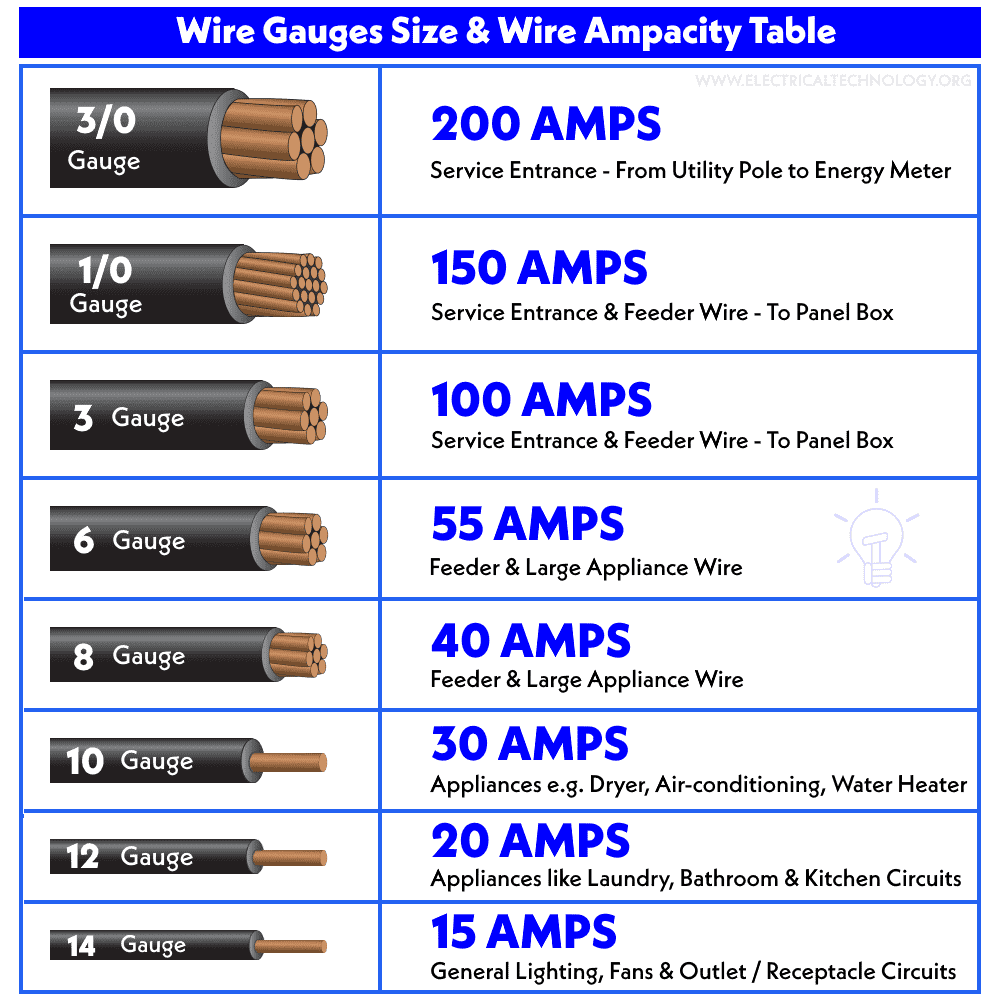
Below is the general table based on NEC – 2020 with wire applications, rated ampacity and AWG wire size for given and specific uses.
| Wire Applications | Rated Ampacity | Wire Gauge – AWG |
| Low-voltage lighting circuits | 10 amps | #18 |
| Light duty Extension cords | 13 amps | #16 |
| General lighting circuits, lamps and fixtures | 15 amps | #14 |
| Kitchen, bathroom, and outdoor outlets and receptacles | 20 amps | #12 |
| Electric water heaters, Electric ranges, stove, ovens, cooktops, dryers, air conditioners, | 30 amps | #10 |
| Heavy duty Cooktops and ranges, EV Charging | 40-50 amps | #6 |
| Commercial Electric furnaces, large electric heaters | 60 amps | #4 |
Resources:
- What is the Correct Wire Size for 100A Breaker and Load?
- How to Determine the Number of Lighting Branch Circuits?
- How to Determine the Number of Branch Circuits? – 3 Ways
- How to Size a Single Phase and Three Phase Transformer in kVA?
- How to Determine the Suitable Size of Inverter for Home Appliances?
- How to Calculate the Right Size of Solar Charge Controller?
- How to Calculate the Right Size Battery for PV System?
- How to Calculate the Number of Panels for a Load without Battery Backup?
- How to Size Panels, Batteries, Charge Controller and Inverter for PV System in Home
- How to Find Power, Voltage & Ampere Rating of Outlet, Receptacle and Plugs
- How to Calculate the Number of Fluorescent Lamps in a Final Sub Circuit?
- How to Calculate the Number of Incandescent Lamps in a Final Sub Circuit?
- How to Calculate the Battery Charging Time & Battery Charging Current ?
- How to Calculate the Floor Area For General Lighting?
- How to Find the Number of Lights on a Single Circuit Breaker?
- How to Find the Number of Outlets on a Single Circuit Breaker?
- How to Size the Earth Conductor, Earthing Lead & Earth Electrodes?
- How to calculate the Cable size for LT & HT Motors?
- How To Locate Faults In Cables? Cable Faults, Types & Causes
- How To Calculate Your Electricity Bill?
Tools:
- Electrical Cable & Wire Size Calculator for Copper & Aluminum
- Wire & Cable Size in AWG Calculator for 1 and 3-Phase Load
- American Wire Gauge “AWG” Chart – Wire Size & Ampacity Table
- American Wire Gauge (AWG) Calculator – AWG Size Chart & Table
- Standard Wire Gauge “SWG” Calculator – SWG Size Chart & Table
Wiring Installations:
- How to Wire 120V & 240V Main Panel? Breaker Box Installation
- How to Wire a Subpanel? Main Lug Installation for 120V/240V
- How to Wire Single-Phase, 230V Consumer Unit with RCD?
- How to Wire a Garage Consumer Unit?
- How to Connect a Portable Generator to the Home Supply – 4 Methods
- How to Connect Automatic UPS / Inverter to the Home Supply System?
- How To: Electrical & Electronics Tutorials
- Basic Electrical Wiring Installation Tutorials
-
 Why is the Long Prong Neutral Instead of the Narrow Prong?
-
 Why is the Neutral Prong or Slot Wider on a Plug or Outlet?
-
 Why are there Grooved Slots in the Pins of Two Pin Plugs?
-
 How to Size a Branch Circuit Conductors with Protection?
-
 How to Size Feeder Conductors with Overcurrent Protection
-
 How to Size Service-Entrance Conductors and Feeder Cables?