What is Power Factor (Cos ϕ) ? Cos fi or P.F Definition & Formulas
Power Factor Definitions and Formulas
In electrical engineering, power factor is only and only related to AC circuits i.e. there is no power factor (P.f) in DC circuits due to zero frequency and phase angle difference (Φ) between current and voltage.
What is Power Factor?
Power factor may be defined by three definitions and formals as follow.
- You may also read: Is Reactive Power Useful?
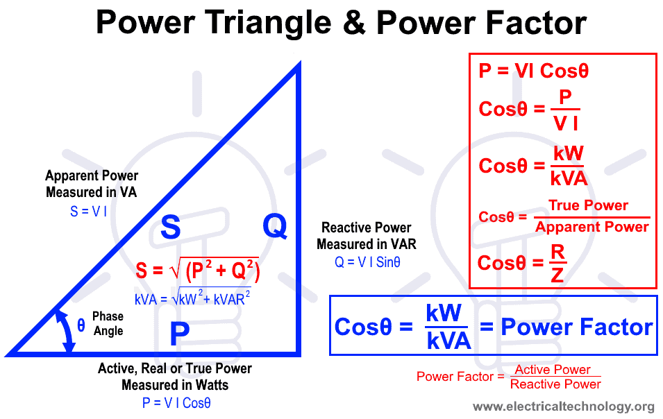
1). The Cosine of angle between Current and Voltage is called Power Factor.
- P = VI Cosθ OR
- Cosθ = P ÷ V I OR
- Cosθ = kW ÷ kVA OR
- Cosθ = True Power ÷ Apparent Power
Where:
- P = Power in Watts
- V = Voltages in Volts
- I = Current in Amperes
- W = Real Power in Watts
- VA = Apparent Power in Volt-Amperes or kVA
- Cosθ = Power factor
2). The ratio between Resistance and Impedance in AC Circuit is known as Power Factor.
Cosθ = R ÷ Z
Where:
- R = Resistance in Ohms (Ω)
- Z = Impedance (Resistance in AC circuits i.e. XL, XC and R known as Inductive reactance, capacitive reactance and resistance respectively) in Ohms (Ω)
- Cosθ = Power factor
Impedance “Z” is the total resistance of AC Circuit i.e.
Z = √ [R2 + (XL + XC)2]
Where:
- XL = 2πfL … L is inductance in Henry
- XC = 1 ÷ 2πfC … C is capacitance in Farads
Related Post: Difference Between Active and Reactive Power
3).The ratio between Active Power and Apparent Power in volts-amperes is called power factor.
- Cosθ = Active Power ÷ Apparent Power
- Cosθ = P ÷ S
- Cosθ = kW ÷ kVA
Where
- kW = P = Real Power in kilo-Watts
- kVA = S = Apparent Power in kilo-Volt-Amperes or Watts
- Cosθ = Power factor
Power Factor Formula in Three Phase AC Circuits
Power Factor Cosθ = P ÷ √3 VL × IL… Line Current & Voltage
Power Factor Cosθ = P ÷ √3 VP × IP… Phase Current & Voltage
Power Factor Triangle and Examples
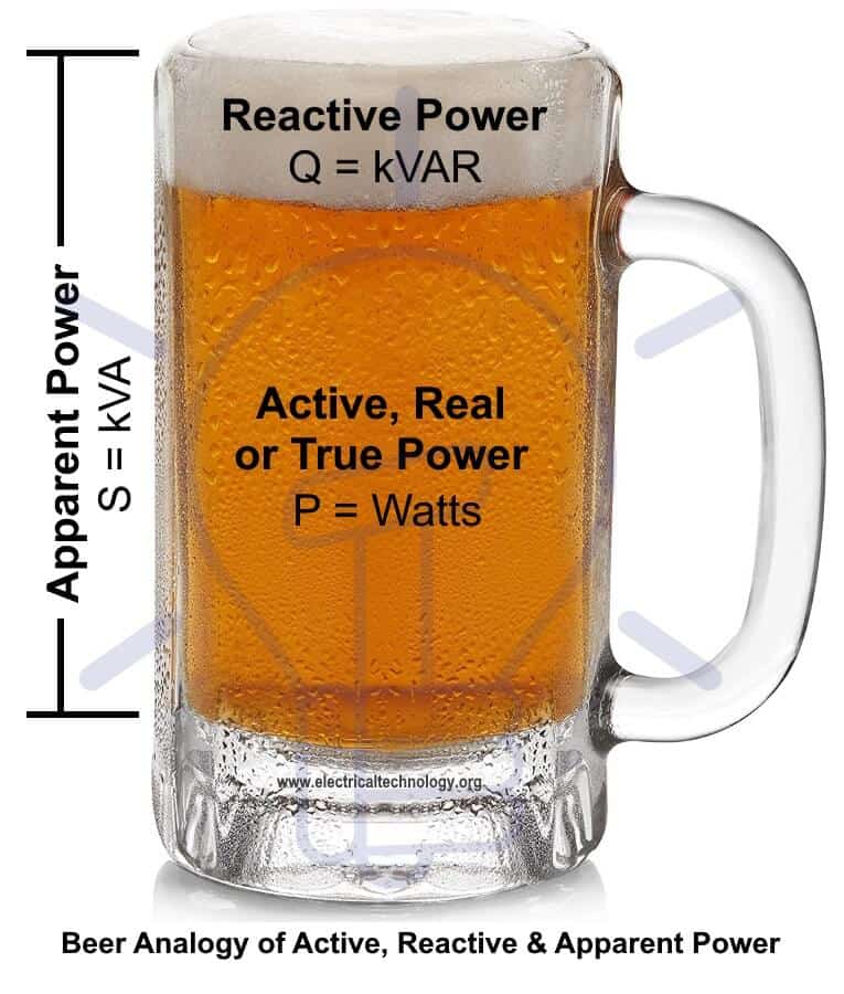
Beer analogy of active or true power, reactive power, apparent power and power factor.
Chips bag analogy of true or real power, reactive power, apparent power and power factor.
In pure resistive circuit, power factor is unity (1) due to zero phase angle difference (Φ) between current and voltage. In pure capacitive circuit, power factor is leading due to the lagging VARs. i.e. Voltage is lagging 90° behind the current. In other words, Current is leading 90° from voltage (Current and voltage are 90° out of phase with each others, where current is leading and voltage is lagging). In pure inductive circuit, power factor is lagging due to the leading VARs i.e. Voltage is leading 90° from current. In other words, Current is lagging begging 90° behind the voltage (Current and voltage are 90° out of phase with each, others where voltage is leading and current is lagging).
Related Posts:
- Causes of Low Power Factor
- Disadvantages of Low Power Factor
- Advantages of Power factor improvement and Correction
- Power Factor improvement Methods with Their advantages & Disadvantages
- Active, Reactive, Apparent and Complex Power.
- Difference Between Active and Reactive Power – Watts vs VA
- How to Calculate the Suitable Capacitor Size in Farads & kVAR for PF Improvement
- How to Convert Capacitor Farads into kVAR & Vice Versa
- Capacitor banks – Characterless and Applications
- What is Electrical Power? Types of Electric Power and their Units
- kVAR to Farad Calculator – How to Convert kVAR to μ-Farads?
- μ-Farad to kVAR Calculator – How to Convert Farads to kVAR?
- Analysis of Reactive Power in Power System
- Is Reactive Power Useful? Importance of Reactive Power
- Introduction of Custom Power Devices For Power Quality Improvement
- What is Static VAR Compensator (SVC)? Construction, Working and Applicators


Simple and easy to understand, thanks
Welcome :)
That’s easy to understand!
Now, what analogy can be given to a capacitor to show that even a capacitor is involved in the concept of Power Factor? It will give an even more clear understanding!
You may check the links at the end of the above post :)
sir i want to save it..how it is possible?<br />easy to perceive,nice way to demonstrate.thanks
i too expected same example from you<br />
I want to download free e-books. so plz invite me to do so.
amiherejohn47 @gmail. com
the total power factor in actual is a product of the displacement power factor(cos[fi]) and the distortion power factor.the distortion power factor is a function of the total harmonic distortion,hence the total power factor of the system decreases on in actual practice on account of the presence of harmonics and other non linearities.
REALY GOOD EXPLICATION…Thanks!!<br />
its banificial for us that’s why thanks
sir plz upload 3 phase transformer 25 kva step down oil immresd self cooled core and winding calculation.
sir plz answer the question its about control i know you can answer it …. which transform we use for convergence ? Laplace transform or Fourier transform or Z transform
Its very simple to understand.I never understand about these three power concept.
Thanks sir.
plzz tel me how to reduce to kvah
Nice article and well explained!
tell me why change the pf of d.g and main sub station.
humko pasand aya
Becuse cos& factor is beetween kw and kva.
I found your perspective on it very informative.