How to Test and Fix the Printed Circuit Board (PCB) Defects?
Diagnosing of Defective Printed Circuit Boards (PCB)
Before delving into the details of a printed circuit board (PCB), there are some basics you need to know about circuits.
Electricity: It is the power provided to every instrument, ranging from small lights to heavy machinery. Electricity is simply the flow of electrons from a higher level to a lower level.
In an electrical circuit, there is always a voltage or current source, components of the circuit, and electricity always flows from a positive voltage level to a negative voltage level.
Voltage, current, resistors, capacitors and inductors are considered the primary elements of any electrical scenario called a circuit. Electrical current can be in two forms: either a sinusoidal AC (alternating) current or simply a straight line called direct or DC current.
In hardware development of electrical circuits, consolidating all components onto a single board or place is called PCB designing.
A Printed Circuit Board (PCB) is the common term used for these electrical boards. In the past, PCBs were developed using a complicated procedure of point-to-point wiring, making these circuits highly susceptible to failure or damage. Later, more accurate design techniques were developed that were more secure.
These days composition of printed circuit board consists of four major components.
- Silkscreen
- Solder Mask
- Copper
- Substrate that is fine fiberglass
Older PCBs were single-layered, but nowadays, multi-layered PCBs are prevalent and used in the market. PCBs are multi-layered because the complexity of electrical circuits has increased.
Newly developed PCBs have high-pitched parts, with many parts being unidentifiable and untestable. Additionally, they involve complex troubleshooting and repairing techniques. Unlike older circuit boards, which could be repaired using automatic test equipment, it is not possible to do so with modern PCBs. Some techniques used for troubleshooting are as follows:
- Related Post: 25 Online PCB Design Tools and Software for EE Students
PCB Troubleshooting Techniques
Testing and fixing defects on a Printed Circuit Board (PCB) typically involves several steps. Here’s a general approach:
- Visual Inspection & Tracking: Start by visually inspecting the PCB for any obvious defects such as burns, breaks, or misplaced components.
- Checking Solder Joints: Examine the solder joints for proper connection and possible defects.
- Checking Integrated Circuits (ICs): Verify the functionality and condition of integrated circuits on the PCB.
- Tracking problems: Identify and track down any issues or abnormalities on the PCB.
- Troubleshooting Discrete Elements: Identify and address any problems with individual components such as resistors, capacitors, and diodes.
- Using Software for Assistance: Utilize software tools to aid in diagnosing and resolving issues.
- Testing for Short Circuits: Use a multimeter in continuity mode to check for short circuits between different traces or components. Ensure the PCB is not powered during this test.
- Testing for Open Circuits: Check for open circuits by testing the continuity of traces and components. Ensure there is no continuity where there should be an open circuit.
- Power-Up Test: Power up the PCB and use a multimeter or oscilloscope to check the voltage levels at different points. This can help identify areas where the voltage is incorrect, indicating a defect.
- Functional Testing: If possible, perform functional testing to check if the PCB is performing its intended function correctly. This may involve using test equipment or simulating inputs to the PCB.
- Component Testing: Test individual components such as resistors, capacitors, and ICs using appropriate testing equipment to ensure they are functioning correctly.
- Repairing Defects: Once defects are identified, repair them by replacing faulty components, re-soldering connections, or repairing traces using a soldering iron and suitable techniques.
- Re-Testing: After repairs, re-test the PCB to ensure the defects have been successfully fixed and that the PCB is functioning correctly.
- Documentation: Document the defects found, repairs made, and test results for future reference.
Many traditional techniques become less effective when dealing with modern circuit boards due to their complexity and compactness.
However, a newly developed VI (Voltage-Current) signature analysis technique has emerged as a powerful method for troubleshooting complex circuit elements. This technique is particularly effective for diagnosing faults in completed circuit elements, offering a valuable tool for modern PCB troubleshooting.
- Related Post: PCB Designing: How To Design a PCB – Example Circuit
Analog Signature Analysis to Test the Unpowered Printed Circuit Boards (PCBs)
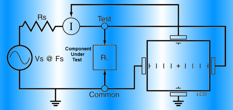
One of the best essential devices used for detailed analysis of faulty components in a circuit is a Curve Tracer. It is a preferred choice for testing PCBs when component signatures or documentation are lost. This test requires no power supply, making it ideal for checking faulty or dead boards, as it is unsafe to power them up.
A sine wave is provided to the particular component under test using two probes. The resulting currents, voltages, and phase shifts are displayed on an LCD. Current is on the y-axis while voltage is on the x-axis, and the resultant trace is displayed as a signature on the screen. To use this device, you need to have a solid theoretical knowledge of the signatures of different components, and a complete understanding of its operation is required.
Strategy to Diagnose a Faulty PCB
There are three different stages to this technique:
- Detection of fault using VI instrument: The VI instrument is used to detect faults. Unidentified high pin counts are tested by applying alternating voltage.
- Locating the faults: This stage involves a detailed analysis to pinpoint the faulty component. Unlike a functionality test, which tests the entire circuit, this stage focuses only on the input and output stages.
-
Replacement of faulty components: In the third stage, new functional components are placed in the circuit after removing the faulty components.
Analysis/Results
In an electrical circuit, all components are either in series, parallel, or a mixed combination (Series-Parallel), making it difficult to identify their signatures. In such scenarios, the most suitable solution is to take a new PCB and compare the signatures of the defective one with the signatures of a functional one.
To compare the signatures, the first step is to gather all the signatures of the defective PCB and, if available, the new functional PCB. If the signatures of the components are not available, they must be measured using a multimeter. This involves measuring voltage, resistance, current, and inductance of every component and then comparing them with the signatures of the defective PCB.
If you have a fully functional PCB, you can take all its signatures using a multimeter. Then, compare these signatures with those of the defective PCB.
The next steps involve troubleshooting and repairing the PCB:
- Refresh all points: Remove any dry or damaged solder and compare signatures. If the signatures match, the fault has been removed. If not, proceed to the next step.
- Track repair: Perform tracking, as there are many tracks in a PCB and there are chances for them to get damaged. If any track is damaged, a jumper wire can be used to repair it.
- Functionality test: Perform a functionality test on every pin of linear integrated circuits (ICs). Check the input and output on every pin of the IC. If it matches with the original datasheet, it is fine. Otherwise, you have to remove that IC.
Related Troubleshooting and Repairing Tutorials
- How To Test Electrical & Electronics Components using a Multimeter?
- How to Find the Value of Burnt Resistor – 4 Methods
- How to Test a Capacitor using Digital and Analog Multimeter – 8 Methods
- How to Test a Diode using Digital & Analog Multimeter – 4 Ways.
- How to Test a Transistor using Multimeter? 4 Ways
- How to test a battery with Test Meter?
- How to Test a Relay? Checking SSR & Coil Relays


It is extremely difficult to know if a circuit board needs repair unless you are a professional and know what to look for. I think this little trick that you mention is going to help people figure out if their circuit board needs repair. While I was reading on http://www.contecdirect.com/services.php I read a list of electronics that use circuit boards to operate. I was surprised to see things like alarms and fire suppression systems on there.
PCBs are very simple to troubleshoot for an experienced one, as there is not much equipment you will need in order to troubleshoot your average printed circuit board repair. The most versatile tool used for troubleshooting PCBs is a multimeter. In cases, when deep troubleshooting is required for PCB repair then we need complex technology to properly troubleshoot a PCB and trace a problem back to its source, like you may need to use something like an LCR meter, an oscilloscope, or a power supply and logic analyzer.
i like it so much for very good explanation with image