Introduction to Series, Parallel and Series-Parallel Connections
Series, Parallel, and Series-Parallel Circuits: A Comparison and Their Applications
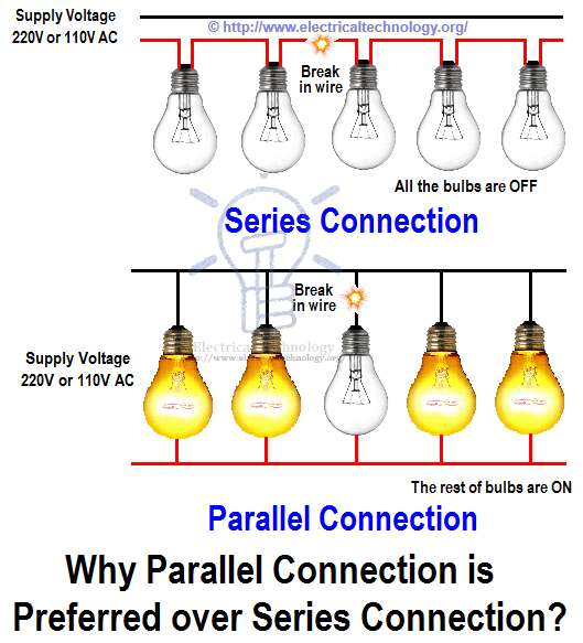
Why is Parallel Connection Mostly Preferred Over Series Connection?
The use, application and importance of series and parallel circuit connection today cannot be over emphasized. The application of series and parallel circuit connection can be evidently seen in our homes, school halls and in our street lights. Some people suggest that the bulbs in their homes should have individual switches.
Well, it’s not a magic when more than three electric bulbs or loads are controlled by one switch. A load is anything i.e. it could be an appliances, electric bulbs or even ceiling fans that consumes electrical energy when connected to a power supply. The electric bulbs, televisions, refrigerators etc. can all be referred to as a load. The bulbs convert electrical energy into light and heat form of energy. Fans convert the electrical energy into mechanical energy.
The type of connection done to our ceiling fans, electric bulbs will determine if they will have a common switch or not. Series circuit connection gives us the opportunity to connect more than two loads to a common switch. Street lights are a very good example of this. Parallel circuit connection makes it possible for us to connect loads to their individual switch.
Both series and parallel circuit connection are good but one is mostly preferred over the other for one reason or the other. Before we talk about the reason why parallel circuit connection is preferred over series connection, let’s recall what series and parallel connections are first.
Series Circuit
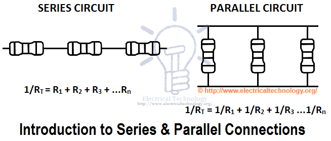
A series circuit is a circuit in which resistors or loads are connected end to end so that the circuit will have only one path through which electric current flows. Thus, when a number of resistors are connected in series, the effective resistance (total resistance in the circuit) is gotten by adding the individual resistance algebraically. That is to say, if we have resistors with resistance R1, R2, R3 …Rn connected in series, then;
Reff = RT = R1 + R2 + R3 + …Rn.
In series connections, the same current flows across all the branches of the circuits, but different voltage across it thus making the resistors to have different voltage across them. Each resistor or load will experience a voltage drop. The applied voltage is equal to the sum of the voltage drop across the different parts of the circuit. Voltage drop is proportional to the resistance current being the same throughout the circuit. When loads are connected in series, the loads will tend to have a common switch. This kind of connection is employed in school halls, street lights.
Application of Series Connection
Some people connect security lights in their homes in series which will make them to have common switch. The problem with this kind of connection is that when a load develops a problem, the other connected system will fail. It’s an all or none type of circuit connection. Till a load gets energy before it delivers it to the other and the one to deliver fails, there will be a black out.
Series circuit connections are common and greatly employed in electrical equipment. The tube filaments in small radios are usually in series. Current controlling devices are always connected in series with the device that they protect. Fuses are connected in series with the device they protect, Automatic house-heating equipment has a thermostat, electromagnetic coils, and safety cut-outs connected in series with a voltage source etc.
Disadvantages of Series Circuit
- The break in the wire, failure or removal of any single lamp will break the circuit and cause all of the others to stop working as there is only one single path of current to flow in the circuit.
- If more lamps are added in series lighting circuit, they will all be reduced in brightness. because voltage are shared in series circuit. If we add more loads in series circuit, the over voltage drop is increases which is not a good sign for electrical appliances protection.
- Series Wiring is “ALL or NONE” type wiring mean all the appliances will work at once or all of them will disconnect if fault occurs at any one of the connected device in series circuit.
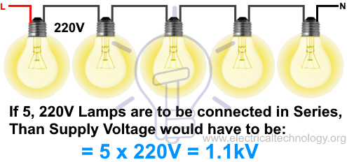
- High supply voltage are needed if we need to add more load (light bulbs, electric heaters, air conditioner etc) in the series circuit. For example, If five, 220V Lamps are to be connected in Series, Than Supply Voltage would have to be: 5 x 220V = 1.1kV.
- The overall series circuit resistance increases (and current decreases) when more load added in the circuit.
- According to future need, only those electrical appliances should be added in the current series circuit if they has the same current rating as current are same at each point in series circuit. However, we know that electrical appliances and devices i.e. light bulbs, fan, heater, air conditioner etc have different current rating, therefore, they can not be connected in series circuit for smooth and efficient operation.

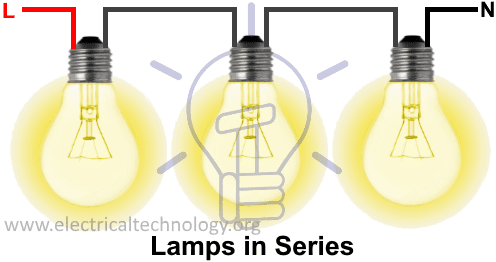
Lights connected in Series

Advantages of Series Connection
- Less size of wire cable is required in series wiring.
- We use to protect the circuit to connect fuse & circuit breakers in series with other appliances.
- Series circuit don’t get overhead easily due to high resistance when more load added in the circuit.
- The lifespan of battery in series circuit is more as compared to parallel.
- It is most simple method of electrical wiring and fault can be easily detect and repair as compared to parallel or series-parallel wiring.
Parallel Circuit
Resistors, loads are said to be connected in parallel when the end of each of the resistors or loads have a common point or junction and the other ends are also connected to a common point or junction. Such circuits are known as parallel circuits.

Unlike the series circuit connection, when finding the total (effective) resistance in a parallel circuit, the reciprocal of the individual resistance is taken. Thus, when a number of resistances are connected in parallel, the reciprocal of the effective resistance is given by the arithmetic or algebraic sum of the reciprocal of the individual resistance.
1/Reff or 1/RT = 1/R1 + 1/R2 + 1/R3 …1/Rn.
Parallel circuit connection have the same voltage flowing across all the branches of the circuits. Different resistors have their individual currents.
Application of Parallel Connection
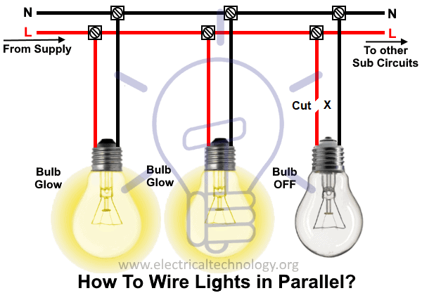
Parallel circuit connection is very common in use. Various lamps and electrical appliances in our homes are connected in parallel so that each of the lamps or bulbs and appliances can be operated independently. For us to have control over the individual lamps or loads, they have to be wired in parallel.
Advantages of Parallel Circuit
- Each connected electrical device and appliance are independent from others. This way, switching ON / OFF a device won’t affect the other appliances and their operation.
- In case of break in the cable or removal of any lamp will not break the all circuits and connected loads, in other words, other lights/lamps and electrical appliances will still work smoothly.
- If more lamps are added in the parallel lighting circuits, they will not be reduced in brightness (as it happens only in series lightning circuits). Because voltage is same at each point in a parallel circuit. In short, they get the same voltage as the source voltage.
- It is possible to add more light fixture and load points in parallel circuits according to future need as far as the circuit is not overloaded.
- Adding additional devices and components wont increase the resistance but will decrease the overall resistance of the circuit especially when high current rating devices are used such as air conditioner and electric heaters.
- parallel wiring is more reliable, safe and simple to use.

Faults in Parallel lighting circuits
Disadvantages of Parallel Connections
- More size of cable and wire is used in parallel lighting wiring circuit.
- More current needed when additional light bulb added in the parallel circuit.
- Battery runs out quicker for DC installation.
- The parallel wiring design is more complex as compare to series wiring.
Related Post: Which Bulb Glows Brighter When Connected in Series and Parallel & Why?
Series-Parallel Connections & Circuits
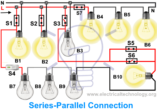
The circuit is series nor parallel in the following fig i.e. it is series-parallel circuit. The first three lamps (B1, B2 & B3) are connected in parallel while switches (S1, S2 & S3) are wired in series accordingly. B7, B8, B9 and B10 are in series with each other while they are parallel with the first three bulbs (B1, B2 & B3) while the switches (S5 & S6) are in parallel connected with Bulb (B10). Also, bulbs (B4, B5 & B6) and switch (S7) are in series with each other while they are in parallel with (B1, B2 & B3) and so on.
As the circuit is combination of series and parallel, We can not simplify the current, voltage, resistance and power by simple Ohm’s Law. We have to apply different theorems like Norton’s, Thevenin’s, maximum power transfer theorem etc. or will simplify the circuit in basic series and parallel circuits to find all those quantities.
Most common of household wiring installation nowadays using this wiring method.
- Related Article: Series, Parallel and Series-Parallel Configuration of Batteries
Comparison Between Series and Parallel Connection
Below in the given table, the main differences between series and parallel connections are shown.
| S No. | Series Circuit | Parallel Circuit |
| Current (I) | Current are same in each point in series circuit:
I1 = I2 = I3 =…. In |
Current are additive in series circuit:
I1 + I2 + I3 +…. In |
| Voltage (V) | Voltage are additive in series circuit:
V1 + V2 + V3 +…. Vn |
Voltages are same in each point in parallel circuit:
V1 = V2 = V3 =…. Vn |
| Resistance (R) & to Find (R) | Resistance are additive in Series Circuit:
R1 + R2 + R3 + …Rn = Reff = RT |
Resistance are divided when more load added in the circuit.
1/RT = 1/R1 + 1/R2 + 1/R3 …1/Rn or I = G1 + G2 + G3 + … Gn |
| To Find Current (I) | I = V1/R1 = V2/R2 = V3/R3 = Vn/Rn | I = V1/R1 + V2/R2 + V3/R3 + Vn/Rn |
| To Find Voltage (V) | V = I1R1 + I2R2 + I3R3 + … InRn | V = I1R1 = I2R2 = I3R3 = … InRn |
| To Find Electric Power (P) |
P = I2R1 + I2R2 + … I2Rn or P = V12/R1 + V22/R2 + … Vn2/Rn |
P = V2/R1 + V2/R2 + … V2/Rn or P = I12R1 + I22R2 + … In2Rn |
| Current & Voltage Divider Rule | V1 = VT (R1/RT), V2 = VT (R2/RT) | I1 = IT (G1/GT), I2 = IT (G2/GT) |
| Paths of flow of Electric Current | Only one path | Two or more paths |
| Brightness of Bulb | Dimmer if added more bulbs (P = V x I) | Brighter due to same voltages |
| If breaks occurs in the circuit | Whole circuit is useless | The rest of the circuit will still work |
| Battery Status | Battery Discharge slowly (Ah Rating of Battery) | Battery Discharge Quickly (Battery Ah Time & Currents) |
| Applications | Used to protect the circuit while connecting fuses and circuit breakers in series with the connected appliances | Used in most of household electrical wiring installations |
Advantages of Parallel Circuit Connection over Series Circuit Connection
A series circuit connection is an all-or-nothing type of connection. This means that if one appliance fails, all the other appliances will also fail. Therefore, this type of connection is suitable only when we want to protect a device.
 When a fuse burns out, typically due to high current, the appliance it protects remains undamaged because the current no longer reaches it. Unlike a series connection, which is all or none, a parallel circuit connection provides the flexibility of individual switches for each load and appliance. Parallel connections offer more resistance to the flow of current compared to series connections.
Two resistors, one with a 100-ohm resistance and the other with 150 ohms, connected in parallel will have less effect on electric current than two resistors with 50-ohm and 40-ohm resistances connected in series. In electronic devices, a parallel connection is paramount. The cells in a power bank are all connected in parallel, which helps electrical energy last longer. These cells have internal resistance, so if they were connected in series, some of the energy would be lost while overcoming the higher internal resistance, as it has a more significant effect in series than in parallel.
Related Posts:
- Why Does the High-Wattage Bulb Glow Dimmer in a Series Circuit?
- Why Does the High-Wattage Bulb Glow Brighter in a Parallel Circuit?
- What is the Objection to having Light Bulbs & Lamps Connected in Series?
- How To wire Light bulbs in Series?
- How To wire Light bulbs in Parallel?
- How To Wire Switches In Series?
- How To Wire Switches in Parallel?


I think that it is good work for knowledge….
Thanks
By – Raj
SERIES CONNECTION IS WRONG ,don’t mention this type of wrong connection
This is the simplest way to understand series and parallel connection. Both connection type has its advantage and disadvantage which will make it easier for people to choose between the two. Of course, the decision highly relies on the need and use.
I think the series circuit operation shown in the image is wrong, if the wire is broken in between all the bulbs will be off.
Yes, all bulbs will be off.
The figure is wrong there. yep
yes wrong
your correct I agree with you and mscm in abudhabi electrical team
PLEASE SEND THE TUTORIAL BOOKS TO MY EMAIL.
THANKS
PLEASE SEND THE TUTORIAL BOOKS TO MY EMAIL.
THANKS
Series is waste and parallel is best
You can wire street lights in series and save on the cost of wire. Connect each lamp in parallel with an inductor. If the lamp burns out; current will pass through the inductor and the rest of the lamps will still work correctly.