STAR-DELTA Starter Motor Starting Method Without Timer
Starting & Controlling of 3-Phase Motor using Semi-Automatic Star-Delta Starter Without Timer
Electric motors are essential components in various industrial applications and play a vital role in powering machines, pumps, compressors, and other equipment. However, when it comes to starting large motors, the initial inrush current can be significantly high, leading to voltage drops and potential damage to the motor windings. That’s why do we need a PLC, VFD, or a motor starter such as a Star-Delta Starter.
To overcome this challenge, engineers have developed various motor starting methods, and one such method is the “Star-Delta Starter.” As we have explained the automatic star-delta starter using timer in the previous post, In this article, we will explore the power and control diagram, working principle and applications of semiautomatic or manual star-delta starter without using a timer.
Related Posts
- Automatic STAR/DELTA Starter Using Timer – Power, Control & Wiring Diagrams
- Reverse/Forward 3-Phase Motors using Start-Delta Starter & Timer – Power & Control Diagrams
- REV-FWD Three Phase Motor using Star/Delta Starter without Timer
Introduction to Star-Delta Starter
A star-delta starter is a widely used method for starting three-phase induction motors. It allows for a gradual reduction of the starting current, reducing the impact on the power supply and the motor itself. Typically, an automatic star-delta starter uses a time delay relay to switch between the star and delta connections of the motor windings. However, in some cases, the use of a timer may not be necessary or practical, especially in applications where simplicity and cost-effectiveness are crucial.
Working Principle of Star-Delta Starter without Timer
The star-delta starter without timer follows a basic principle: the motor starts in a star configuration, and after a predefined time, it switches to the delta configuration. This methods uses when a time delay timer is faulty or not available during the emergency operation of large motors.
Unlike the conventional star-delta starter, this method does not use a time delay relay. Instead, it relies on manual control for the switching process e.g. using push button switches for manual operation for transferring the mains connection from Star to Delta.
Star Connection
During the starting process, the motor windings are initially connected in a star (Y) configuration. In the star connection, each winding receives the full line voltage (VL) across them. This configuration allows the motor to draw reduced current compared to a direct-on-line start.
Delta Connection
After a specific period (usually a few seconds) of running in star mode, the motor windings are switched to a delta (Δ) configuration. In the delta connection, each winding receives the line voltage divided by the square root of 3 (√3) across them. This results in an increase in the current but provides higher torque, allowing the motor to reach its full speed.
Related Posts:
- Starting & Stopping of 3-Phase Motor from More than One Place – Power & Control Diagrams
- How to Start & Stop a 3-Phase Motor Using Direct-On-Line (DOL) Starter?
- Controlling of 3-Phase Motor from More than Two Places – Power & Control Diagrams
Wiring, Power & Control Diagrams of Star-Delta Starter
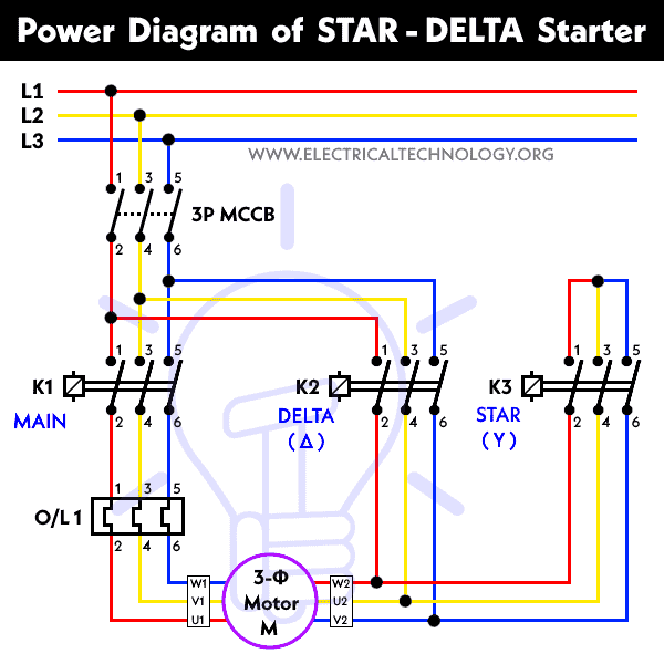
Power Diagram:
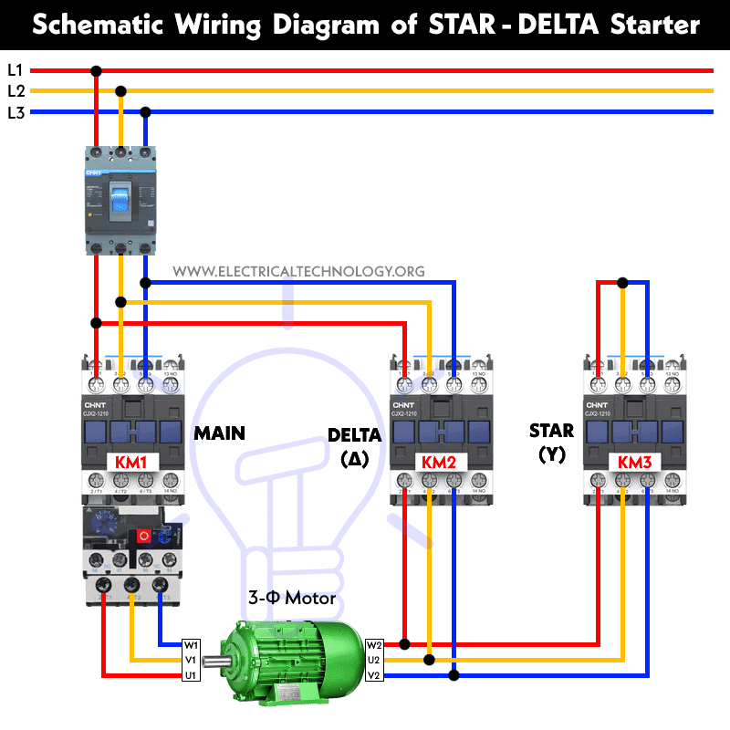
Schematic Wiring Diagram:
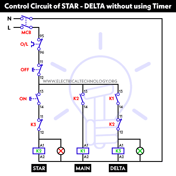
Control Circuit Diagram:
Control Wiring Diagram:

Related Posts
- Automatic Sequential Motor Control Circuit – Power & Control Diagrams
- Reverse / Forward Circuit for 3-Phase Motors – Power & Control Diagrams
- Three Phase Slip Ring Rotor Starter – Control & Power Diagrams
Manual Control Procedure
The manual control procedure for the star-delta starter without timer is relatively simple. It involves the following steps:
- Initial State: The motor is at rest, and the windings are disconnected.
- Star Connection: Press the “Start” button or close the start contactor. This connects the motor windings in a star configuration.
- Star Mode Operation: The motor runs in the star configuration for a predetermined time to reduce the starting current.
- Delta Connection: After the time delay (manually measured or estimated), press the “Changeover or pushbutton” button or close the changeover contactor. This switches the motor windings from star to delta configuration.
- Delta Mode Operation: The motor runs in the delta configuration, reaching its full speed and providing the necessary torque for the intended load.
- Stopping the Motor: To stop the motor, press the “Stop” button or open the main contactor.
Advantages
The Star-Delta Starter without Timer offers several advantages:
- The absence of a time delay relay simplifies the control circuit. It reduces the chances of timer-related failures and eliminates the need for adjusting the timer based on motor size and specifications.
- The removal of the timer component reduces the overall cost of the starter. This makes it an attractive option, especially for small to medium-sized motor applications, where cost plays a significant role in equipment selection.
- With fewer components involved, the star-delta starter without timer improves the overall reliability of the motor starting process. The manual control procedure is straightforward and less prone to electronic or electrical malfunctions.
- The simplified design reduces maintenance efforts and costs. Technicians can easily troubleshoot and replace faulty components if necessary, without dealing with intricate timer circuits.
Applications
The Star-Delta Starter without Timer finds application in various industries, including:
- Agriculture: Irrigation pumps and agricultural machinery.
- Manufacturing: Fans, blowers, conveyors, and compressors.
- Mining: Crushers and large conveyor systems.
- Oil and Gas: Pumps and compressors for fluid transportation.
- Water Treatment: Water pumps and purification systems.
Abbreviations:
- R ,Y, B = Red, Yellow, Blue or Brown, Black, Gray ( 3 Phase Lines L1, L2, L3)
- C.B & MCCB = General Circuit Breaker & Molded Case breakers
- Mains = Main Supply
- Y = Star
- Δ = Delta
- O/L = Over Load Relay
- NO = Normally Open
- NC = Normally Closed K1 = Contactor (Contactor coil) K1/NO = Contactor Holding Coil (Normally Open)
- K1 , K2, K3 = Contactors
Related Tutorials and Resources used in Power & Control Wiring Diagrams for Motors
- Star – Delta Motor Control Circuit Using Delta – DVP 14SS2 Series PLC
- Star – Delta Motor Control Using Schneider Zelio Logic PLC Smart Relay
- Star – Delta Starter Motor Control Circuit Using S7-1200 PLC
- Automatic Star – Delta Starter Motor Control Circuit Using LOGO! V8 PLC
- Star – Delta Motor Control Circuit Using Omron PLC ZEN Programming Relay
- What is Motor Starter? Types of Motor Starters and Motor Starting Methods
- What is Soft Starter? Its Working, Diagram and Applications
- Direct Online Starter – DOL Starter Wiring Diagram for Motors
- What is a Contactor ? Types, Working and Applications
- Three Phase Motor Power & Control Wiring Diagrams


Very educative and important information. Keep it up. Thank you.
I like it and will love more of it
Sir m new to this site plz. Tell me the hole table of circuit breakers acc. and There range of use.
Okk don’t worry we will give you whole knowledge about this in next article
Special thanks to wasim khan.very educative and important information.keep it up.
Dear K.Mark. Thanks for appreciation . =D
i like it God bless you
Can anyone please help…
I have a 3 phase grain mill for grinding corn etc (farming implications) but only have a single phase supply. Can I get the mill to work on the single phase and HOW ?
All replies much appreciated.
There must a 3 phase motor inside,disconnect its wires and give supply through a separate connections from a VFD drive of any good brand, VFD drives capable to run three phase motors from single phase supply.
Yes yu can make it
How it works it real life w/o a timer, it that means that you’ll operate it manually to change from delta to wye?
yes that is what it mean, and you can do that with the configuration of another button.
Your a special teacher! I`ll disturb 4 this things myn!
hi thanks for help me so now i ask you same questions what about on control citric you use two line means L1 AND L2 YOU SAY L2 IS NEUTRAL OR NOT
– OUR CONTRACTOR OF CONTACT POINT BY 380V SO CAN YOU TELLON THE A1 AND L2 IS PHASE AND NEUTRAL CAN I INSERT OR FOR BOTH A1 AND A2 CAN INSERT TWO PHASE
Nice dear buhat achy
Please add me
Star delta diagram
please explain me how that control circuit works
i am electric engg from GRD Jharkhand
This means that we stil ned to manualy pres a swetch to change d comection to delta ryt?
Dear friends,
I need to run the motor on vfd with star delta circuit pls suggest me circuit.
please i need a help. i operate an Ingersollrand air compressor that is controlled by a star delta starter. the motor runs for some minutes and the control circuit will trip but starts when start push button was pressed. also, the timer relay just went off after the compressor ran for 4 cycles. what should i do because one component keeps going off after another. Please advice me. my email is ejike.njoku2@yahoo.com. Thanks
thanks sir , very educative information for us ,, so plz next time give us a star delta control circuit with timer
We have already added this post… Search in the above links….
Bhai Thnxs For This Butt Tell me about Timer yar How to Attach time with star and delta
pls add me
Need update always
it’s good
Dear Sir please let me know how to make connotation for star delta with VFD control use for chiller water pump thank you
This doesn’t work , motor first starts in delta according to this connection then it will work on star , that is un acceptable solution
SIR U R SAYING K1 ON ON WHEN S1 ON AND HOLDS ITSELF BUT WHEN STAR RUNNING IS IT TRUE THAT THE MITOR WILL ON . HOW ITS POSSIBLE WHEN STARTING IN STAR MODE U R NOT ON K1 (MAIN ) CONTACTOR ?????????
\
sir I want to know that if we are going to connect a motor directly in star or delta connection without a stater thaen how we can make sure that which connection is suitale for the motor star or delta? if star why? if delta why? explain the reason also and explain it for havey motor and also for normal 75 w 3 phase motor
Dear I need easy wiring dia gram 220 to 380 we are using Stamford alternator pls send me any I always burned AVR
Dear Leeman you may use capacitor for Three Phase motor.phase sequence will change
very useful topic ……………..
i want to be receiving news letters
Can i have the operation please and a typical example where this can be used
sir tell me s1 and s2
since i hv new 3phase induction motor .i need ur help to do connection with power & control circuit with push bottom but without timer.
sir,
can u show the power and control diagram for 3phase induction motor with push bottom but without timer