ControlElectrical WiringMotors
Three Phase Motor Power & Control Wiring Diagrams
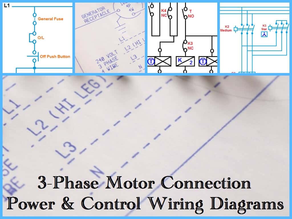
Three Phase Motor Power & Control Wiring Diagrams

Three Phase Motor Connection Schematic, Power and Control Wiring Installation Diagrams.
- Star-Delta (Y-Δ) 3-phase Motor Starting Method by Automatic star-delta starter with Timer.
- Three Phase Motor Connection STAR/DELTA Without Timer – Power & Control Diagrams
- Three Phase Motor Connection Star/Delta (Y-Δ) Reverse / Forward with – Timer Power & Control Diagram
- Starting & Stopping of 3-Phase Motor from more than One Place Power & Control diagrams
- Control 3-Phase Motor from more than Two buttons – Power & Control Diagrams
- ON / OFF Three-Phase Motor Connection Power & Control Schematic and Wiring Diagrams
- Three Phase Motor Connection Reverse and Forward – Power and Control wiring diagrams
- Three Phase Slip Ring Rotor Starter – Control & Power Diagrams
- Two Speeds One Direction Three Phase Motor Connection Power and Control Diagrams
- Two Speeds, Two Directions Multispeed 3-phase Motor – Power & Control Diagrams
- Multi Speed 3-Phase Motor, 3 Speeds, 1 Direction – Power & Control Diagrams
- One line Diagram of Simple Contactor circuit.
- Three Phase Electrical Wiring Installation in Home – IEC & NEC
- How to Connect a Portable Generator to Home Supply System (Three Methods)
- A Simple Circuit Diagram of Contactor with Three Phase Motor.
Resources:
- What is Motor Starter? Types of Motor Starters and Motor Starting Methods
- What is Soft Starter? Its Working, Diagram and Applications
- Direct Online Starter – DOL Starter Wiring Diagram for Motors
- What is a Contactor ? Types, Working and Applications
You may also read
- Electrical Wiring and Installation Tutorials
- Basic Home Electrical Wiring installation Diagrams
- Single Phase & Three Phase Wiring Diagrams (1-Phase & 3-Phase Wiring)
- Batteries Wiring Connections and Diagrams
- Solar Panel Wiring & Installation Diagrams
- UPS / Inverter Wiring Diagrams & Connection


How to check Resistance for Wire and coil explain briefly Thankyou
we can use 5 KVA meggar for wire insulation (120 sqmm to 300 sq-mm control cable) & above
1-Phase to Earth
2-Phase to Phase
For 2.5 mm and above Control Cable
we use Multimeter
1-Connect both end of Single wire to Multimeter terminal & multimeter Set to Continuity we can found actual resistance of wire after few sec.
sir.. ct & pt na ni upr name plate tuti gai hoy to kemni khabr pade k te ct che k pt che ???
I need Idea a bout AC Speed Control use IGBT to contol 3 phase motor .
thanks
Please provide the auto changeover scheme circuit between two DOL feeders whether i can also manually start any of two DOL feeders by selector switch.
Waiting for your valuable reply.
thank you
how do you convert a 3-phase wyn motor to run with single phase power supply?
use transformer input 380,output 220 ACV.
Electrical
Please provide me the Star-Delta 3-phase Motor Starting Method by semiAutomatic star-delta starter with Timer.
What process wire lay
i like this site. Keep up the great work. Thanks for a wonderful website
Dear Sir/Madam
i want star delta power and control wiring diagram with full detail if you give me this please
full drawing means from starting to end point
like as no/nc of timer and connector please give on my mail id
Best Regard
Shilpesh Patel
9974818099
send me ACB buscoupler control wiring with using Under voltage coil. 2 incomer one buscoupler.
i want a sequential two motors operating in opposite direction
how can I wire 2 motors to run in turns on a compressor. not timer !!!
when the one motor filled the tank it must give the next sickle to the other motor and so on
input 120v-,9.OA,60Hz output usbx2 each 5Vdc/1A (total 2A max) outlet x4 each 120v-,8A, 6oHz(total 8A Max)
A client has two motors which he wants to run them in two modes
I, Manual mode
Ii, Automatic mode.
On the manual mode, motor A and motor B can be controlled separately by selector switch.
On the automatic mode, motor A has to run for 3 minute then motor B comes on also.
Can you help me with the controlled diagram
Yes
I have a Master Flow PVM105 replacement motor for my attic roof fan. Can I reverse the rotation?
please can you provide me with a two speed motor starter which changes from high speed to low speed without stopping,I need both power and control circuit…thank you
Control penal statar Wiring contract manpower fhul hai fin working
Thank you so much for the descriptive wiring and circuit diagrams. It helped me a lot.