Automatic Street Light Control Circuit using LDR & Transistor BC 547
Basic Electronic Project – Automatic Street Light Control Circuit
Following is yet another simple Electrical/Electronics project for automatic street light control systems especially for students, newbies and hobbyists.
Features:
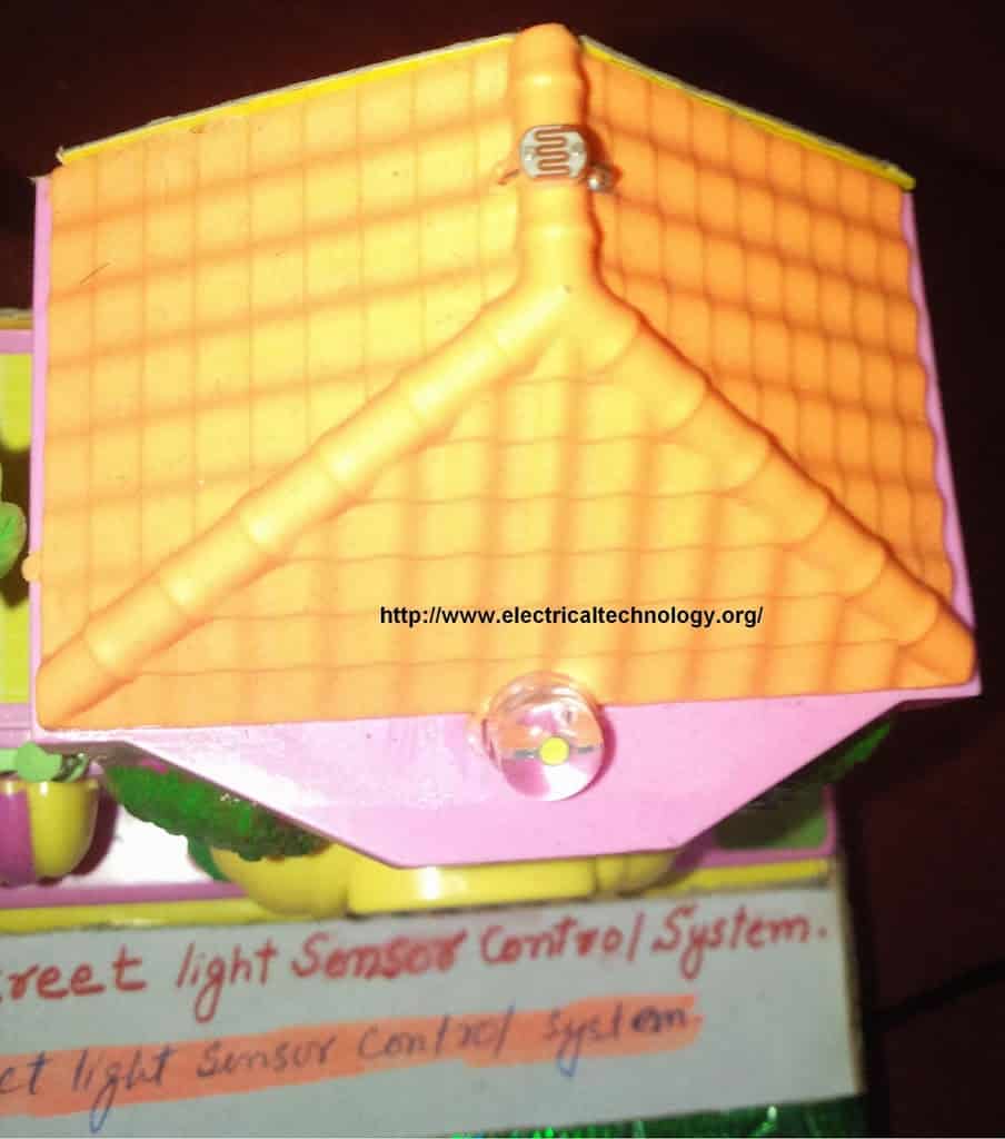
- It is a dark detector circuit based on LDR and a transistor (BC-547 NPN) which automatically switches ON and OFF the street light system.
- It automatically switches ON street lights when the sunlight goes below the visible region of our eyes. (e.g. in the evening after sunset).
- It automatically switches OFF the lights when sunlight falls on it ( i.e. on LDR ) e.g. in the morning, the sensor called LDR (Light Dependent Resistor) senses the light just like our eyes and deactivates the circuit.
Related Simple Projects:
Advantages:
- The automatic operation of street light controlling systems help to reduce the energy consumption as compared to the manually operated street light controlling operations. This is because there is a delay in the earlier switching operations both in morning (during sunrise) and evening (during sunset).
- On sunny and rainy days, ON and OFF time is noticeably differ which is one of the major disadvantages of using timer circuits or manual operation for switching the street light system.
Enough … Now let’s begin the step by step guide to make the circuit of the basic project.
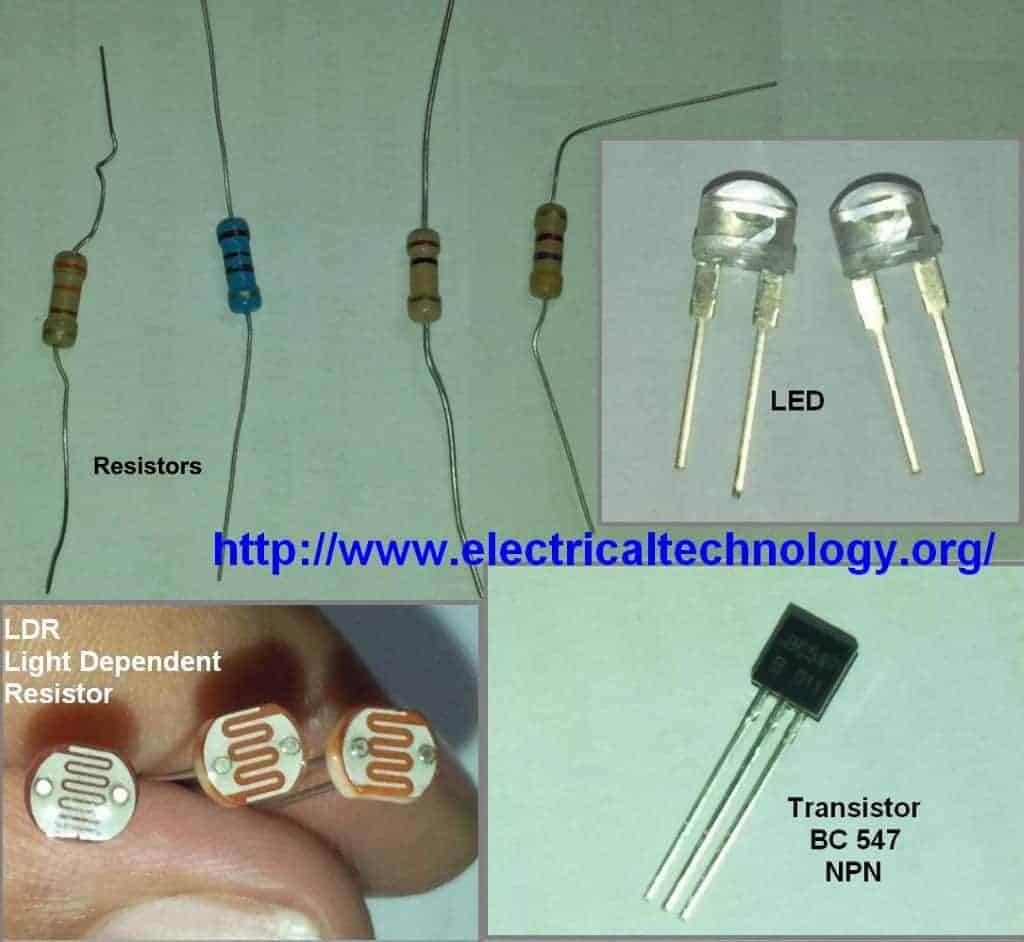
Components Required:
- LDR – Light Dependent Resistor
- 2 Nos. of transistors. (NPN transistor – BC547 or BC147 or BC548)
- Resistor- 1kΩ, 100kΩ, 330 Ohm & 470 ohms.
- Light emitting diode (LED) – Any color
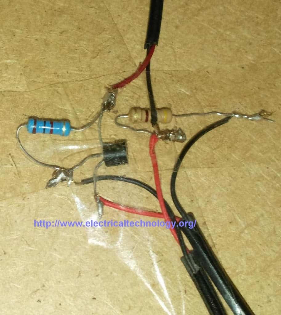
- Connecting wires – (Use single-core plastic-coated wire of 0.6mm diameter (the standard size) or any wire used in computer networking).
- Power supply-6V or 9V
Related Post: Magnet levitation simple Electrical Project
Procedure
- Insert first transistor Q1-BC547 (NPN) on breadboard (or general PCB) as shown in the circuit diagram 1.
- Connect another transistor Q2- BC547 (NPN) on the breadboard as in step 1.
- Connect wires across the emitter pin of both transistors and -Ve terminal of battery (lowest/bottom row of breadboard.)
- Connect a wire across the Collector pin of transistor Q1 and Base pin of transistor Q2.
- Connect a resistor 1K across the positive terminal of battery (topmost row of breadboard) and Collector pin of transistor Q1.
- Connect Light Dependent Resistor (LDR) across the positive terminal of battery (topmost row of breadboard) and base terminal of transistor Q1.
- Insert a resistor- 330 Ohm across base pin of transistor Q1 and negative terminal of battery (lowest bottom row of breadboard).
- Connect a resistor 330R across the positive terminal of battery (topmost row of breadboard) and anode terminal of LED (Light emitting diode) & Connect the cathode terminal of LED to Collector pin of transistor Q2.
Related Post: Mini Air-Cooler System from 12V Fan (Homemade form Trash)
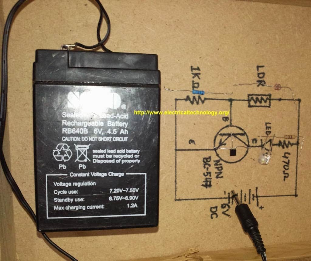
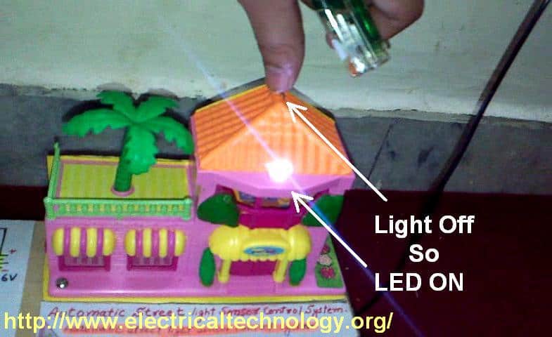
The simple circuit is ready for testing now. Connect 6V to 9V battery terminals to the circuit as shown in fig and see the output. As you block light falling on the Light dependent resistor(LDR), the LED glows and vice versa.
LED GLOWS EVEN IN LESS DARKNESS. Use torch light or lighter if the LED glows in less darkness. In addition, you can try to adjust the sensitivity of this circuit by using a variable resistor in place of R1-300 Ohm. You may use other resistances as well, (e.g., 1KΩ, 10KΩ and 100KΩ, etc.)
Pictorial Story: (Click images to enlarge)
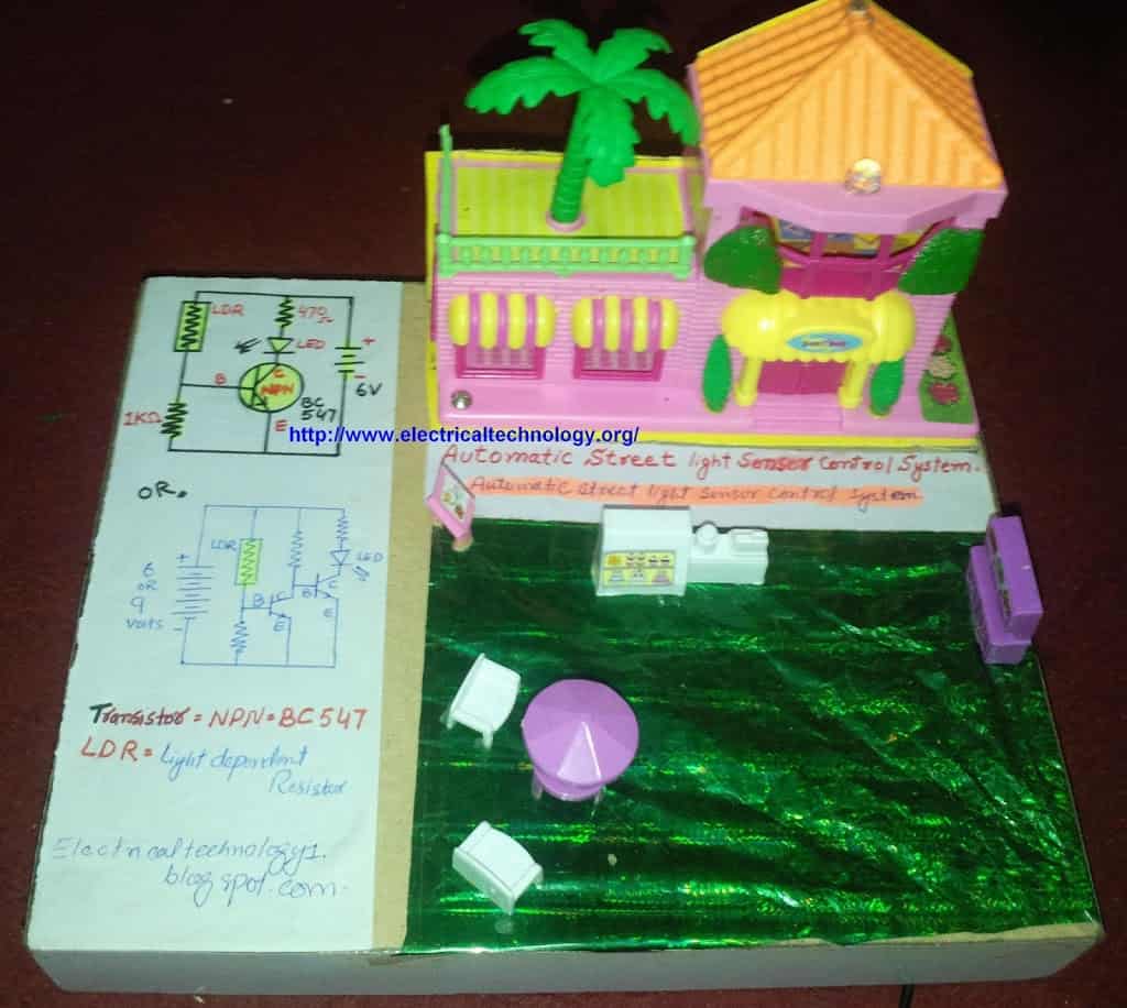
Components & Schematic Circuit Diagrams for Automatic Street Light Control System
![]()
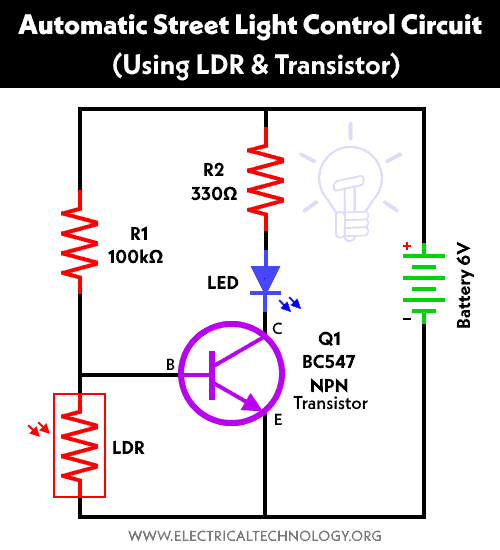
Circuit Diagram 1. Automatic Street Light Control System.(Sensor using LDR & Transistor BC 547.). We have tried and Cicuit#1 in this tutorial but you may also try the second one (Circuit#2) mentioned below ight after circuit no 1.
Circuit Diagram 2 . Automatic Street Light Control System using LDR and two nos. of Transistor BC 547.
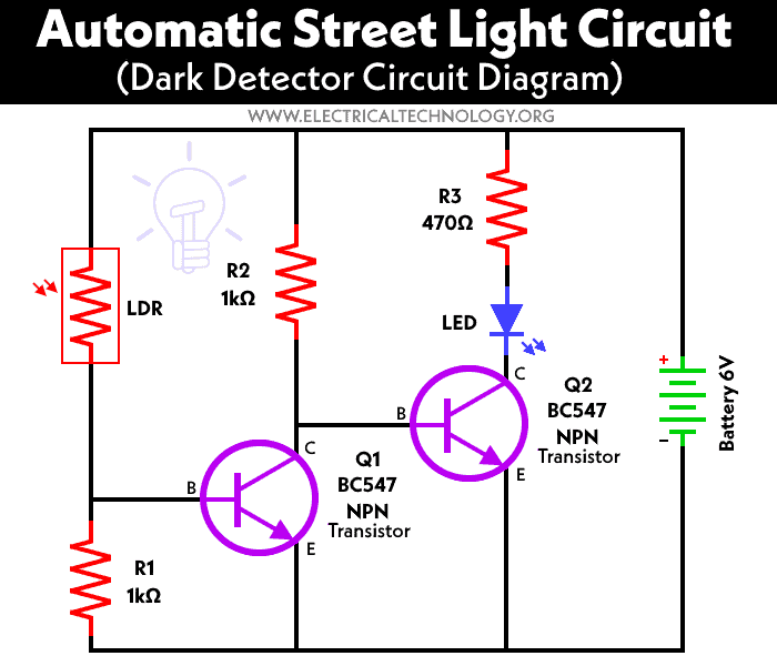

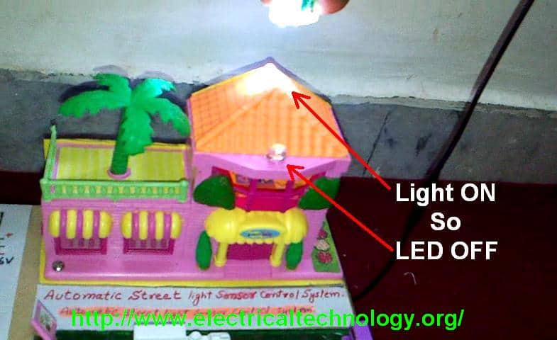
In the dark (e.g. when light is blocked to the LDR), the LED is ON i.e. the LED is ON.
Snapshot taken out from the Video.
For more basic electrical and electronics engineering project tutorials, visit: Simple Electrical & Electronics Projects Library
Some Basic Electronic Projects Circuit Diagrams based on LDR
- Automatic Street Light Control System using LDR
- Electronic Eye Circuit – Based on LDR
- Automatic LED Emergency Light Circuit using LDR
- Automatic Night Lamp Using LDR


brother this ckt only work for very small load , if you wana going to do it paractically fo 25watt or above load then your bulb/load will start flickering , so there for paractical point of view i suggest to use 555 time , which can easily handle 100watt load with out flickering
Agree…But this is a simple project…I have also project report..where all Circuit diagrams available i.e. for small, normal and large loads..
Please send or give us the link.
Please send or give us the link so that we can use it.
Please I need it if possible
Friend You can easily controll hight wattage Items by the using of 6VDC Relay Instead of 330 ohm Resistance and LED. By Using 2nd Circuit Displayed by Wasim Khan
@ Bhatti Soft kindly paste a link of the crkt displayed by wasim khan <br />thanks
do you know what is the main reason of flickering that is the light which is on the load feedback the LDR that's why an error-full control system will created automatically.you need to separate the light source from your LDR.LDRshouldn't response on it's own circuit load and of-course you need to add relay or traic with very little labor to make it a strong circuit..BEST OF LUCK :)
Can u give me the diagram using relay
please guys I have as a final project"automatic street lights" using ldr, microcontroller,pwm,EE555.. can any one help please ?
No dOubt eFForts aRe goOd nd simpLe…thnx buDDy.. :)<br /><br />
Welcome Dear…. Thanks 4 appreciation
Dear can u help me for final year project of electrical technology<br />
am doing the same project will u send total project pdf ……please
If you face any problem.,then ask here…Thanks
It is very helpful for beginners like us. Thax a lot for sharing. Bro kindly provide a simple circuit, I need to control street light 220 v with using LDR. In sunlight my street light turns on & at night turns off automatically, for that kindly provide a circuit.
sir, i have a problem i made “automatic street light circuit” according to circuit diagram 1 but there is a problem is that when i cover LDR the LED off and when i did not covered it its ligt on
how can i solve this problem plz reply me quic as posible am waiting….!
Good work, in present time to balance the lighting consumption it is very necessary to employ this lighting technique. Led lighting is good source of light; it will require less electricity and also provide much brighter light as compare to other traditional lighting sources. <br /><br />Reference: <a href="http://www.adattsi.com/induction-lighting/high-bay" rel="nofollow">http://www.adattsi.com/
Super.Now a days in solar streetlight systems some peoples are using voltage based Controllers.Is this right( i meant it voltage sensors).<br />If this is right please furnish the details about this type of circuit diagram.
can this actually be incorporated practically in the streets..? how would one accomplish it using this simple circuit and installing it into real street lamps?<br />
I have a complete project on this…. i will upload and share pdf link…..Thhanks
plz upload soon & provide link here.
It'd be very simple actually. Swap out the low wattage components used in this example with some higher wattage ones, replace the battery with a 120/6 volt transformer + a rectifier and filter capacitor & put the coil for a contactor that would switch the mains power for the street light on and off in series with the transistor. <br /><br />The circuit would be almost identical to the
I personally liked using the services of electricians-capetown.com for their great services, as they are truly professional, knowledgeable and trustworthy.
i have to control around 6 tubelights in a room using this circuit bro<br />can u plz help me out with the circuit<br /><br />regards
We will update the circuit…Thanks
Good day Sir,
I am working as an ship electrician , My problem is that the Insulation Resistance Monitor is Normal but the phase indicator bulb (the 3 bulbs) the two are not so bright then the other one is very bright , can you please help me to correct this problem..any reply from you sir is highly appreciated..
Thank you very much
can we used relay instead of led?
Which one and for which purpose?
relay insted of led????<br />both are very different from each other
i'm not sure if i'm right, does the Q2 in the circuit 2 should be a pnp transistor instead?? please help me understand . thanks…
I have used BC-547 NPN [both]
i'm now currently trying out the 2nd circuit, but then it didn't work out… i don't know if i mistakenly connect the components, but i've tried dozen times already…can you please help me show the full circuit of it on breadboard? thanks
Have you tried the first one….if not then try it…..by the way…i have tried these both circuits and its working properly….Also, I will upload the video to YouTube and then share the link here.
hi<br />can some one suggest me how to incorporate with AC outdoor light for 100 watt…..Please suggest me how to use 12v relay to use higher load. Please provide me circuit diagram where AC out can be define there.<br />If you send me diagram on email ID, It will great for me.<br /><br />Regards<br />rabikant09@rediffmail.com
wait i realized that circuit 2 will turn on the led when there is no light on the ldr, while ciruit 1 turns on the led when there is light?? light decreases the ldr's resistance right???
circuit 1 differs to circuit 2… circuit 1 is led on when there is light while circuit 2 is led on when there is no light… Is this correct??? resistance decreases with light right?
when there is bright outside , resistance decreases <br />and when there is dark outside, resistance increases (LDR)
how can i make it more sensetive.. ………<br /> …mine led is also glowing in room light .. i have to provide an torch light to LDR to switch off<br />
can i use a 9 volt battery??<br />plz replay
Is there any project in which led glows in brightness .. What are its uses …
Hi all.<br />First circuit is wrong. There is no doubt any expert eye can detect its mistake. :)<br />I am an electronics engineer
I Don't think so,,,
hi can you tell me the function of each element you have used like what is the use of transistors in this ckt and resistors …..i would be very grateful if u wud help me out.<br />thnx in advance
can we use this ckt for ac 230v or more voltage<br /><br /><br />
ya but u have to tuse more elements likr step down transformer,relay,555IC for ac source.<br />
Simple and cheap. Can you give the details of the battery charger including overcharging protection.?
In Electronics Store, You can Easily find a Battery charger about (6-9V, 0.6 – 1.2A)
I would also likely to know about the use of transistor in the circuits…….. It would be very helpful
can u please suggest some human and vehicle detection sensors used in street light????????
Thank you so much with regard to giving me an update on this topic on your blog..Thanks for your time and consideration of other individuals by making this web site available.
brother i do but when led on when ldr in light and when dark led off plz help…
same thing happen with me also… have u got any idea ragarding this problem..<br />tell me pliz if u find out..<br />
Which Circuit did you make..1 or 2 ???
please send me a block diagram of automatic street light control system (LDR as the sensor).
i cant get the output for second circuit LED is continously glowing,<br />and for the first circuit output is reverse. what to do?<br />
Check your connection…btw..I will Upload step by step video.. :)
thanks i am waiting for it
Please help, what is the use of the transistor BC 547? and the other components? please help. i will be using this for my project..
Which transistor is used
Which circuit did you try… Make sure to connect all the components in proper direction….
well done …………..(i'm sri lanka )<br />
What is the value of 6V battery in Amperes?
i did this circuit and i have to answer 2 questions :<br />1- how can u improve your design ? <br />2- what other application that can be implemented ?<br />i dont know what to answers lol ..plz help<br />
hey , will anyone help me ?? i amn't getting the output , before i block the LDR the led is glowing , hw can i coorect thiss??<br />
hey wil anyone help me to do this doucument plzz
nice one i want to do this one
Brilliant post! You explained everything quite intelligently. I will follow all the steps for automatically turning ON and OFF my garden lights, or I will simply forward this blog , thank you! You were a great help.
I have finished first circuit but output get reverse ,light is ON ,LED is ON ,please help…
Did you try the circuit in proper format as stated above? Check the direction and polarity…
plese upload video before 1 hour.
Site is under maintenance….
any change inLDR, i will used 9v battery.
Did you try the 1st or second one?
I will used FIRST circuit.
mine is not working can you explain how does this work THANKS
How can I improve this simple DC project with AC 240V
How can I improve this simple DC project with AC 240V.thanks.
Can you give a brief working of the circuit asap?thank you
this will work as a light finding sensor but this is not light control system. Please make sure about it.
I GOT THE CIRCUIT RIGHT WHEN I USED PNP INSTEAD OF NPN TRANSISTOR
Sir, can you please explain the functions and importances of use of TRANSISTOR Q1-BC547 (NPN) and RESISTORS R1(1kohm) & R2(470ohm) [circuit 1] used in making this, in simple language , because i wanted to preform this project as my investigatory project (12class) and for practical & viva purpose i have to explain it and provide the answers of questions. { i hope u can understand my problem }.
Sir can anyone tell about OLR connections? Do we have apotential free NO(it becomes NC when OLR trips) contacts in OLR?
Kindly notify me of new post by email.
Thanks
Please Subscribe and We will… Thanks
Sir, can you please explain the functions and importances of use of TRANSISTOR Q1-BC547 (NPN) and RESISTORS R1(1kohm) & R2(470ohm) [circuit 1] used in making this, in simple language , because i wanted to preform this project as my investigatory project (12class) and for practical & viva purpose i have to explain it and provide the answers of questions. { i hope u can understand my problem }
Interesting circuit! well done guys
can i connect multiple leds?
i need some guidance about ma final project…it’s about street lights
well,I think I got it, please help to get enough guidance on vehicle movement street light project
I’ve done this project but there is light on the led is also on. when light is off the led is also off. waste project, waste of time, waste of money.
can I use use LEDs at distances of about 10 cms apart from eachother
Light is flickering what I have to do now to stop flickering ..?
can u plz give me a detailed working bcoz i have to made i for project and i have to write working and have to give viva so plz teel me the working of circuit 2
can anyone please tell me the reason why 470 ohm resistance is used particularly? why not some other value resistance?
please do reply soon
I built this circuit but the circuit work in the opposite direction. When there is sun the light switches on. And when it is dark the light switches off. What am I doing wrong?
Can you pls tell me how it works?
Means not procedure but working.
Great article. Study another comprehensive article on how to design energy efficient automatic street light using micro-controller here : http://engineerexperiences.com/auto-street-light.html
Nice work. What if I want to build an automatic street light controller for bigger projects , what should i change and what should i include.
Many people have asked this question but i saw no reply
pls explain and give circuit diagram automatic street light control system use in 230v for real home.
It is very nice and simple project.please send the video of this project.thanks
Sir I have designed the circuit as same in the diagram2 using 2 330 ohm and 1 1,000 ohm resistors.But the Led glows even in light.only when I introduce a torch light very close to LDR the Led dims.What should I do to increase it’s sensitivity? please help me
plz someone should help me with full complete project report on solar powered LED street light with auto intensity control on this mail abubakarmuktar@gmail.com.
Thank you my fellow brothers
two flat surfaces with a sensor that responds to the circuit being broken causing a light to go on at a fairly close remote location and eventually triggering a smartphone app. please advise to a sensor that would fit this simple application… thank you
Keep posting such Informative articles. Thanks for the updates.